
NHTSA ID Number: 11028093
Manufacturer Communication Number: 01-002-26
TSB/Document Date: 2026-02-03
Summary
Some vehicles may exihibit a vibration in the accelerator pedal and steering wheel when accelerating during a sharp left-hand turn. An abnormal noise may also be heard from the footwell area. This may be caused by insufficient clearance between the engine mount stopper rubber and the engine mount bracket. Customer may state: - Vehicle shudders/vibrates on left turns, most often when accelerating from a stop or entering a driveway. - They feel a pop or grind in the accelerator pedal when the vibration occurs. - They hear a rumbling or grinding noise, mainly from the right side, during the left-turn shudder. NOTE: The condition does not occur at shallow steering angles or when the vehicle is stationary and the steering effort remains unchanged when the vibration and noise are present.
If the PDF is very large, it may not load in the preview below.
Some older TSBs had multiple PDFs — visit the NHTSA Website to view all PDFs.
If the TSB PDF does not show, download or view it on the NHTSA Website.
Click on the (+) Plus Sign
Then Click on Associated Document(s)
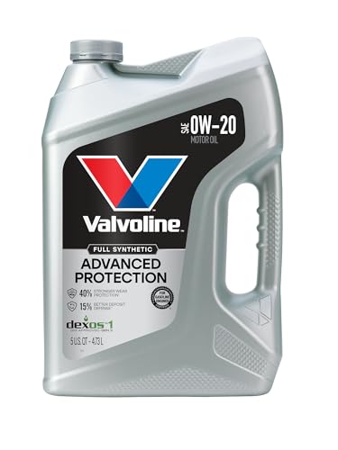
- Advanced protection against the four main causes of engine...
- Delivers 40% stronger wear protection than industry...
- Provides 15% better deposit defense vs. industry standards...
- Up to 2.5X better heat protection vs. industry standards to...
- Engineered for excellent low-temperature flow, reducing...
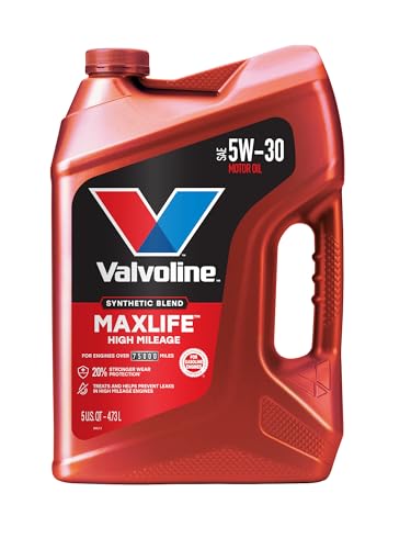
- Formulated for engines with 75,000 miles or more, Valvoline...
- Delivers 20% better wear protection and 15% better sludge...
- Extra detergents safeguard against friction, corrosion and...
- Advanced friction-fighting additives help maximize...
- Provides performance benefits for high mileage, new and...
Search NHTSA Database for Recalls
Search NHTSA Database for Vehicle Investigations
View Latest Vehicle Investigations
Search NHTSA Database for Vehicle Complaints
View Latest Vehicle Complaints
TSB/Document ID: 01-002-26
Replacement Service Bulletin Number:
MFR Communication Date: 2026-02-03
MFR Internal Campaign ID/Software Version:
Communication Type: Service Bulletin/Repair Instructions
NHTSA Components: ENGINE
MFR Component System:
MFR Component Subsystem:
Previous TSB | Next TSB |
BULLETIN NOTES
This bulletin supersedes the previously issued bulletin(s) listed below. The changes are noted in Red.
Previous TSBs:
Date(s) Issued:
01-007/25
11/14/25
APPLICABLE MODEL(S)/VINS
2024-2026 CX-90 (All) with VINS lower than JM3KK******353975 (produced before September 11, 2025)
2025-2026 CX-70 (All) with VINS lower than JM3KJ******200374 (produced before September 11, 2025)
DESCRIPTION
Some vehicles may exihibit a vibration in the accelerator pedal and steering wheel when accelerating during a sharp lefthand turn. An abnormal noise may also be heard from the footwell area. This may be caused by insufficient clearance
between the engine mount stopper rubber and the engine mount bracket.
Customer may state:
- Vehicle shudders/vibrates on left turns, most often when accelerating from a stop or entering a driveway.
- They feel a pop or grind in the accelerator pedal when the vibration occurs.
- They hear a rumbling or grinding noise, mainly from the right side, during the left-turn shudder.
NOTE: The condition does not occur at shallow steering angles or when the vehicle is stationary and the steering effort
remains unchanged when the vibration and noise are present.
Customers having this concern should have their vehicle repaired using the following repair procedure.
REPAIR PROCEDURE
1. Verify the customer concern.
NOTE: DO NOT use power tools in this procedure. Use hand tools only.
2. Disconnect the negative battery terminal using the procedure in [NEGATIVE BATTERY TERMINAL
DISCONNECTION/CONNECTION].
3. Remove the engine cover.
Page 1 of 17
01/09/2026 12:44 PM tlawrenc
4. Remove the heat insulator.
(1) Engine mount nut
(2) Stud bolt
(3) Engine mount bracket
(4) Stopper rubber
(5) Engine mount
(6) Engine mount bolt
5. Remove the right front (RF) tire using the procedure in [FRONT UNDER COVER REMOVAL/INSTALLATION].
6. Remove the front under covers (splash shields) No.1, No.2, and No.3 using the steps in [FRONT UNDER COVER
REMOVAL/INSTALLATION].
7. Remove the mudguard bolt and fastener.
8. Remove the right-side (passenger side) front splash shield No.2 using the procedure in [FRONT UNDER COVER
REMOVAL/INSTALLATION].
9. Remove the nut (left image (1)) from the engine mount (left image (3)) and loosen but DO NOT remove the engine
mount bolts (left image (2), right image (1)).
Page 2 of 17
01/09/2026 12:44 PM tlawrenc
NOTE: The engine mount bolts are easily accessed with a 36-inch (90 cm) extension from above. A 1/2 inch drive is
recommended because it flexes less.
10. Remove the engine mount stud.
Page 3 of 17
01/09/2026 12:44 PM tlawrenc
11. Support the engine with a jack, but DO NOT lift. A screw jack is recommended as it is more precise with lifting and
lowering. NOTE: When jacking up the oil pan, insert a cushioning material between the jack and the pan (e.g., a large
wooden block that extends beyond the oil pan and protects it).
NOTE: If using a transmission jack, make sure it does not interfere with the crossmember.
12. Insert the cushioning material between the jack and the oil pan.
13. Loosen, but DO NOT remove the three right-side member bracket (subframe) bolts (1).
14. Loosen, but DO NOT remove the two crossmember bolts (2).
15. Remove the bolt that holds the heater hose bracket (3) to the right engine mount.
NOTE: The outer bolts (circled yellow (2)) are for crossmember (subframe) bolts. The center bolt between these 2 is the
bolt that goes through the engine mount (when looking straight up at the A-arm). The hole through the A-arm bracket is
where a tool extension goes through to remove the bolt for the mount. This is the bolt in step 2 below (yellow circle).
•
Page 4 of 17
01/09/2026 12:44 PM tlawrenc
View from underside (right side).
Page 5 of 17
01/09/2026 12:44 PM tlawrenc
Page 6 of 17
01/09/2026 12:44 PM tlawrenc
16. Remove the four engine mount bolts (one from underneath and the three from the top that were loosened.
17. Lift the engine approximately 0.4 inch (10 mm) to unload the mount.
NOTE: Ensure you lift only enough so that a slight gap appears between the engine mount and the engine bracket.
(1) Engine mount bracket
(2) Engine mount
(3) To the extent that no gap forms (i.e., no load
on the mount)
Page 7 of 17
01/09/2026 12:44 PM tlawrenc
18. Remove the engine mount.
a. Pull the engine mount out toward the wheelhouse.
b. Replace the stopper rubber (2) with a modified part.
NOTE: Ensure correct orientation and that the marked side faces upward; no adhesive is required.
Page 8 of 17
01/09/2026 12:44 PM tlawrenc
c. Use a scraper to remove any debris (1)
d. Install the stopper rubber with the marked side facing upward.
NOTE: The stopper rubber is black, identical to the original part.
Marking colors (3):
KRY0-39-040: Pink (PHEV)
KSY0-39-040: Blue (H3T)
Page 9 of 17
01/09/2026 12:44 PM tlawrenc
e. Install so that it hooks onto the tabs (2).
f. Tighten the engine mount bolts to the specified torque with the vehicle lifted.
NOTE: DO NOT install the engine mount stud (3) at this time.
Symbol
Content
Servicing order
Temporarily tighten
36.9 ft·lbf (50 N·m; 1 kgf·m)
g. Tighten the right-side member bracket bolts.
h. Tighten the crossmember bolts.
i. Tighten the heater hose bracket bolt.
j. Remove the jack after all nuts and bolts are tightened.
NOTE: The engine mount stud should NOT be installed at this time.
k. Lower the vehicle until all tires contact the ground except for the right front.
NOTE: The right front tire should NOT be installed at this time.
Page 10 of 17
01/09/2026 12:44 PM tlawrenc
l. Use a floor jack to lift the engine until the mount and bracket touch.
NOTE: When jacking up the oil pan, place cushioning material (e.g., a rubber pad or wooden block) between the
jack and the pan.
m. Verify the stud bolts and bracket holes are aligned.
n. Install the engine mount stud and torque it to spec.
NOTE: The nut should NOT be installed at this time.
Symbol
Content
25.1 ft·lbf (34 N·m; 3.45 kgf·m)
Page 11 of 17
01/09/2026 12:44 PM tlawrenc
o. Ensure a zero-contact position before tightening.
1) Zero-touch position (1).
2) Lightly push the engine-mount stud (2) with your finger; if it can be moved only slightly, you’ve reached
the 0-touch position. If it moves freely without much resistance, lower the engine slightly and recheck.
Page 12 of 17
01/09/2026 12:44 PM tlawrenc
3) Verify that the stud (3) and the engine-bracket bolt holes are aligned in the same positions as shown in
the photo.
■
■
If they are not correctly aligned even in the zero-touch position, shift the stud bolts or the engine laterally to
achieve proper alignment.
DO NOT over-lift or under-lift the engine during tightening.
NOTE: Before tightening, ensure that the engine mount and engine bracket are in a zero contact (0touch position), and that the position of the stud bolt and the bolt hole in the engine
bracket matches the OK position shown in the photo. If the position is not in the OK location even
in the zero contact (0-touch position), manually adjust the engine position. Be careful not to tighten
the nut while the engine is excessively jacked up, as this may lead to loosening of the
fastening. Also, avoid tightening the nut when the engine mount and engine bracket are excessively
pressed together (i.e., when the engine is not jacked up enough), as this may result in excessively
small clearance between the engine bracket and the stopper rubber.
Page 13 of 17
01/09/2026 12:44 PM tlawrenc
NOTE: The image below shows an engine that has not been lifted enough (1) or an engine that has been
lifted too high (2).
4) Lightly tighten the mount nut to 5 ft-lbs (6.8 Nm) on the engine mount stud.
5) Raise the vehicle and measure the gap (left image (1) between the engine bracket (right image (2) and
the stopper rubber (right image (1) using a taper gauge or stacked feeler gauges.
Page 14 of 17
01/09/2026 12:44 PM tlawrenc
Engine
PYUL
Clearance
Suggested Feeler Gauge Combination
0.18 in (4.5 mm)
Order
Size (in)
Size (mm)
1 (Top)
0.0250 in
0.635 mm
2
0.0240 in
0.610 mm
3
0.0230 in
0.584 mm
4
0.0220 in
0.559 mm
5
0.0050 in
0.127 mm
6
0.0180 in
0.457 mm
7
0.0190 in
0.483 mm
8
0.0200 in
0.508 mm
9 (Bottom)
0.0210 in
0.533 mm
Total Thickness
0.1770 in (4.496 mm)
NOTE: Insert the feeler gauges in the suggested
order—thickest on the outside, thinnest in the center—to
reduce the risk of damaging the thinner strip.
H3T
0.15 in (3.8 mm) Order
Size (in)
Size (mm)
1 (Top)
0.032 in
0.813 mm
2
0.025 in
0.635 mm
3
0.026 in
0.660 mm
4
0.009 in
0.229 mm
5
0.028 in
0.711 mm
6 (Bottom)
0.030 in
0.762 mm
Total Thickness
0.150 in (3.810 mm)
NOTE: Insert the feeler gauges in the suggested
order—thickest on the outside, thinnest in the center—to
reduce the risk of damaging the thinner strip.
• If the gap is below the specified value, return to the previous step and recheck that the stud bolts and engine
bracket are aligned in the correct position, then adjust their alignment.
• If you cannot achieve the required gap by adjusting only the right engine mount, remove the nuts that secure the
left engine mount and engine bracket, and shift the left mount to place it in the centered position, as shown for the
left mount (no gap measurement is required on the left side).
• If you still cannot adjust the gap within specification after adjusting both engine mounts, replace both engine
mounts—performing the replacement one side at a time, following this procedure. Loosen the crossmember bolts
one side at a time; loosening both sides simultaneously may cause wheel-alignment deviation.
• When replacing with a new engine mount, it is not necessary to transfer the stopper rubber to the new engine
mount.
19. Install the right front (RF) tire using the procedure in [FRONT UNDER COVER REMOVAL/INSTALLATION].
Page 15 of 17
01/09/2026 12:44 PM tlawrenc
20. Lower the vehicle fully to the ground.
21. Tighten the engine mount nuts to the specified torque with the vehicle's full weight resting on its tires.
22. Install the mudguard bolts and fasteners.
23. Install the right-side (passenger side) front splash shield No.2 using the procedure in [FRONT UNDER COVER
REMOVAL/INSTALLATION].
24. Install the front under covers No.1, No.2, and No.3 using the steps in [FRONT UNDER COVER REMOVAL/
INSTALLATION].
25. Install the right front (RF) tire using the procedure in [FRONT UNDER COVER REMOVAL/INSTALLATION].
26. Install the heat insulator bolts.
27. Install the engine cover.
28. Reconnect the negative battery terminal using the procedure in [NEGATIVE BATTERY TERMINAL
DISCONNECTION/CONNECTION].
29. Verify the repair.
PARTS INFORMATION
Parts Number
Description
Q'ty
Notes
1
PHEV (Pink dot)
1
H3T (Blue dot)
Q'ty
Notes
Rubber No.1, Eng. Mtg.
NOTE: Right engine mount
1
PHEV
1
H3T
Rubber (L), Engine Mt.
NOTE: Left engine mount
1
PHEV
1
H3T
KRY0-39-040
Rub-E/Mtg; RH, Stopper
KSY0-39-040
Order only when necessary
Parts Number
KR9P-39-040*
KS0E-39-040*
KR9P-39-050*
KS0E-39-050*
Description
NOTE: If the adjustment of both engine mounts does not bring them within the specified range, replace both engine
mounts.
Page 16 of 17
01/09/2026 12:44 PM tlawrenc
WARRANTY INFORMATION
NOTE:
• This warranty information applies only to verified customer complaints on vehicles eligible for warranty repair.
• This repair will be covered under Mazda’s New Vehicle Limited Warranty term.
• Additional diagnostic time cannot be claimed for this repair.
Symptom Code
82
Damage Code
97
Causal Part No.
KRY0-39-040 or KSY0-39-040
Quantity
1
Replace right engine mount stopper rubber (PHEV)
XXX37ERX 2.3H
Replace right engine mount stopper rubber (H3T)
XXX37FRX 2.4H
Replace right engine mount stopper rubber + readjust right engine mount
installation position (PHEV)
XXX37GRX 2.7H
Replace right engine mount stopper rubber + readjust right engine mount
installation position (H3T)
XXX37HRX 2.8H
Replace right engine mount stopper rubber + readjust right engine mount
Operation No. and installation position + adjust left engine mount installation position (PHEV)
Labor Hours
Replace right engine mount stopper rubber + readjust right engine mount
installation position + adjust left engine mount installation position (H3T)
Period Covered
XXX37KRX 3.2H
XXX37LRX 3.3H
Replace right engine mount stopper rubber + readjust right engine mount
installation position + adjust left engine mount installation position + replace
both engine mounts (PHEV)
XXX37MRX 5.7H
Replace right engine mount stopper rubber + readjust right engine mount
installation position + adjust left engine mount installation position + replace
both engine mounts (H3T)
XXX37NRX 5.8H
Basic Warranty Period
NOTE: Claim other parts except causal part as related parts
Page 17 of 17
01/09/2026 12:44 PM tlawrenc

- CEL Doctor: The ANCEL AD310 is one of the best-selling OBD II scanners on the market and is recommended by Scotty Kilmer, a YouTuber and auto mechanic. It can easily determine the cause of the check engine light coming on. After repairing the vehicle's problems, it can quickly read and clear diagnostic trouble codes of emission system, read live data & hard memory data, view freeze frame, I/M monitor readiness and collect vehicle information.
- Sturdy and Compact: Equipped with a 2.5 foot cable made of very thick, flexible insulation. It is important to have a sturdy scanner as it can easily fall to the ground when working in a car. The AD310 OBD2 scanner is a well-constructed mechanic tool with a sleek design. It weighs 12 ounces and measures 8.9 x 6.9 x 1.4 inches. Thanks to its compact design and light weight, transporting the device is not a problem. The buttons are clearly labelled and the screen is large and displays results clearly.
- Accurate Fast and Easy to Use: The AD310 scanner can help you or your mechanic understand if your car is in good condition, provides exceptionally accurate and fast results, reads and clears engine trouble emission codes in seconds after you fixed the problem. This device will let you know immediately and fix the problem right away without any car knowledge. No need for batteries or a charger, get power directly from the OBDII Data Link Connector in your vehicle.
- OBDII Protocols and Car Compatibility: Many cheap scan tools do not really support all OBD2 protocols. AD310 scanner as it can support all OBDII protocols such as KWP2000, J1850 VPW, ISO9141, J1850 PWM and CAN. This device also has extensive vehicle compatibility with 1996 US-based, 2000 EU-based and Asian cars, light trucks, SUVs, as well as newer OBD2 and CAN vehicles both domestic and foreign. Pls confirm with our customer service whether it is compatible with your vehicle before purchasing.
- Home Necessity and Worthy to Own: This is an excellent code reader to travel or home with as it weighs less and it is compact in design. You can easily slide it in your backpack as you head to the garage, or put it on the dashboard, this will be a great fit for you. The AD310 is not only portable, but also accurate and fast in performance. Moreover, it covers various car brands and is suitable for people who just need a code reader to check their car.

- Multi-Functions - Practical Multi-Functions OBD2 code reader features built-in OBD2 DTC lookup library, which help you to determine the cause of the engine light, read code, erase code, view freeze frame, I/M ready, vehicle information, data flow, real-time curve, get vehicle speed information, calculate load value, engine coolant temperature, get engine speed.
- Wide Capability - Supports 9 protocols compatible with most 1996 US-Based, 2000 EU-Based and Asian cars, and newer OBD II & CAN domestic or import vehicles. Supports 6 languages - English,German, Dutch, Spanish, French, Italian.
- 2.8" LCD Display - Designed with a clear display 2.8" Large LCD screen - white backlight and contrast adjustment. No need any battery or charger, OBD reader gets the power directly from your vehicle through the OBDII Data Link Connector.
- Compact Design - Car diagnostic scanner is equipped with a 2.5 feet long cable and made of a very thick flexible insulator.There are 6 buttons on OBD2 Scanner:scroll up/down,enter/exit and buttons that quick query VIN vehicle number& the DTC fault code.
- ABS / Airbag codes NOT Supported - It is able to read and clear check engine information which is part of OBDII system, but it cannot work with non-OBDII systems, including ABS / Airbag / Oil Service Light, etc.

- 【Your Personal CEL Doctor – Read & Clear Engine Codes】The NT301 OBD2 scanner lets you read diagnostic trouble codes (DTCs), check em-issions readiness, turn off your Check Engine Light (CEL) or MIL, reset monitors, and view live data streams. It retrieves your vehicle's VIN instantly. Like all standard OBD2 scanners, it clears codes only after repairs are completed—if the issue persists, the code will return. Designed for DIYers who want to understand what’s really going on under the hood.
- 【Easy Code Reading – Just Plug & Play】Simply plug into the OBD2 port, turn the ignition to “ON” (engine off), and select the correct menu: Select OBDII-> Wait for seconds-> Select Read codes. For accurate results, ensure your vehicle is compatible and the OBD2 port is free from damage or wiring issues. No batteries needed— powered directly by your car.
- 【Live Data Graphing & Accuracy for Most OBD2 Vehicles】View and log live sensor data in graph form—monitor oxygen sensors, fuel trims, coolant temp, RPM, and more. Spot trends and suspicious values in real time. Compatible with most 1996+ gasoline cars, light trucks, and SUVs sold in the U.S., as well as many 2000+ European and Asian models. Also works on 12V diesel vehicles equipped with OBD2.
- 【S-mog Check Helper – Know Your Readiness Status at a Glance】With dedicated I/M readiness hotkeys and a simple Red-Yellow-Green LED indicator, you’ll instantly know if your vehicle is ready for em-issions testing. Built-in speaker provides audio feedback. No guesswork—just confidence before you head to the test center.
- 【A Must-Have Tool for Every Home Mechanic】Compact, rugged, and ready to use right out of the box. The 2.8” color screen is easy to read, even in daylight. No charging or setup required—just plug into the 16-pin DLC and start diagnosing. Recommended by professional mechanics on YouTube and trusted by DIYers worldwide.
Last update on 2026-03-24 / Affiliate links / Images from Amazon Product Advertising API
This product presentation was made with AAWP plugin.