
NHTSA ID Number: 11028164
Manufacturer Communication Number: TSB 26-2021
TSB/Document Date: 2026-02-04
Summary
This article supersedes TSB 25-2156 to update the Service Procedure and Labor Time Allowance. Some of the vehicles listed in the Model statement above may exhibit diagnostic trouble codes (DTCs) C1001:31, U3000:89, and/or U3000:49 stored in the image processing module A (IPMA) and at least one of the following conditions: - "Front Camera Fault Service Required" message - Pre-collision assist inoperative - Adaptive cruise control inoperative - Front windshield camera alignment routine fails to complete This may be due to a connection issue between the IPMA Camera and the IPMA.
If the PDF is very large, it may not load in the preview below.
Some older TSBs had multiple PDFs — visit the NHTSA Website to view all PDFs.
If the TSB PDF does not show, download or view it on the NHTSA Website.
Click on the (+) Plus Sign
Then Click on Associated Document(s)
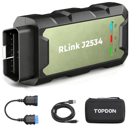
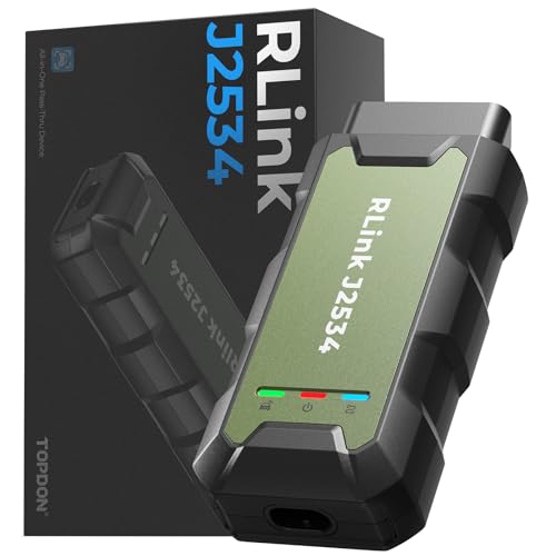
- Advanced VCI Box, Industry-leading J2534 Pass-Thru...
- High-Speed OEM-Level Diagnostics & Programming: Unlock true...
- Coverage for 17 Car Brands & Ultra Reliability: Works...
- User-Friendly RLink Platform & Expert Support: TOPDON’s...
- 6.6 ft USB-C Cable & Portable Storage Case: The RLink J...
Search NHTSA Database for Recalls
Search NHTSA Database for Vehicle Investigations
View Latest Vehicle Investigations
Search NHTSA Database for Vehicle Complaints
View Latest Vehicle Complaints
TSB/Document ID: TSB 26-2021
Replacement Service Bulletin Number:
MFR Communication Date: 2026-01-31
MFR Internal Campaign ID/Software Version:
Communication Type: Service Bulletin/Repair Instructions
NHTSA Components: FORWARD COLLISION AVOIDANCE: ADAPTIVE CRUISE CONTROL
MFR Component System:
MFR Component Subsystem:
Previous TSB | Next TSB |
TECHNICAL SERVICE BULLETIN
Various Driver Assistance System Warning Messages - DTCs C1001:31, U3000:89, And/Or U3000:49 Stored
In The IPMA
26-2021
29 January 2026
This bulletin supersedes 25-2156. Reason for update: updated service procedure to clarify repair direction based on MFAL code (steps 24 to 30), and increased labor
allowance accordingly
Model:
Ford
2021-2023 Mustang Mach-E
Markets: North American markets only
Issue: Some of the vehicles listed in the Model statement above may exhibit DTCs C1001:31, U3000:89, and/or U3000:49 stored in the IPMA and at least one of the
following conditions:
• "Front Camera Fault Service Required" message
• Pre-collision assist inoperative
• Adaptive cruise control inoperative
• Front windshield camera alignment routine fails to complete
This may be due to a connection issue between the IPMA camera and the IPMA.
Action: For vehicles that meet all of the criteria in the Issue and Model statements, follow the Service Procedure to repair the connection between the IPMA camera
and IPMA.
Parts
Service Part Number Claim Quantity Package Order Quantity Description
164-R9343
As Needed
As Needed
3M™ Film Tape 9343 (Rotunda Part number)
Obtain Locally
As Needed
As Needed
Parts - Parts To Inspect And Replace Only If Necessary
Service Part
Number
Claim
Quantity
Package Order
Quantity
Description
LJ8Z-14D202-U
Only If
Necessary
Only If Necessary
LJ8Z-14F662-B
Only If
Necessary
Only If Necessary
LJ8Z-14D202W
Only If
Necessary
Only If Necessary
ML3Z-19H406B
Only If
Necessary
Only If Necessary
19H405
Only If
Necessary
Only If Necessary Image Processing Module A (IPMA) - Refer To The Parts
Catalog For The VIN Specific Application
Note
IPMA Camera To A-Pillar Coaxial Cable
A-Pillar To IPMA Coaxial Cable
For Vehicles Built With Minor Feature Codes
HKLAG, HKLAH, And/Or J3QAD
A-Pillar to IPMA Coaxial Cable
For Vehicles Built With Minor Feature Codes
HKLAF And/Or J3QAA
Image Processing Module A (IPMA) Camera
Service part numbers and "number in package" quantity may change after publication, thus also affecting the "package order quantity". Refer to the parts catalog for the
latest information.
Claim Quantity refers to the total number of individual pieces required to repair the vehicle.
Package Order Quantity refers to the amount of the service part number package(s) required to repair the vehicle.
Number In Package refers to the number of individual pieces included in a service part number package, also known as unit of issue (UOI).
Only If Necessary indicates the part is not mandatory. Refer to the Service Procedure to determine the inspection/inclusion criteria.
Warranty Status: Warranty coverage limits and policies are not altered by a TSB. Warranty coverage limits are determined by the identified causal part.
Labor Times
Operation
No.
Description
2021-2023 Mustang Mach-E: Retrieve DTCs Inspect And Repair Following The Service Procedure (Do Not Use With Any
Other Labor Operations)
MT262021
Time
Actual Time Up To 7.0
Hrs.
Repair/Claim Coding
Causal Part:
14D202
Condition Code: b4
Service Procedure
1. Check the IPMA for software updates using the latest software level of the FDRS scan tool. Is there a software update available for the IPMA?
1. Yes - download and run the "IPMA – Image Processing Module A (IPMA) Software Update" app. Proceed to Step 2.
2. No - proceed to Step 3
2. Did the software update correct the condition?
1. Yes - repair is complete.
2. No - proceed to Step 3
3. Are DTCs C1001:31 and/or U3000:89 stored in the IPMA or were recently stored in the vehicle's 60-Day vehicle health alert/ DTChistory?
NOTE: The vehicle's 60-Day vehicle health alert/DTC history (if applicable) can be found in the PTS > Connected Vehicle > Connected Vehicle Home.
1. Yes - inspect the coaxial cables between the IPMA and the IPMA camera for loose connections. Perform wiggle test to check connectors C900 and
C9128 for being loose. If no loose connections are present, proceed to Step 4. If loose connections are present, reconnect and proceed to Step 5.
2. No - proceed to Step 30.
4. Power the vehicle on and wait 30 seconds. Clear and retrieve DTCs. Are C1001:31 and/or U3000:89 present in the IPMA?
1. Yes - proceed to Step 6.
2. No - the issue is intermittent. Replace both sections of coaxial cable running from the IPMA camera to the IPMA following Steps 6-17 and Steps 19-28,
then proceeding to Step 29.
5. Power the vehicle on and wait 30 seconds. Clear and retrieve DTCs. Are C1001:31 and/or U3000:89 present in the IPMA?
1. Yes - proceed to Step 6.
2. No - proceed to Step 30.
6. Replace the coaxial cable running from the IPMA camera to C900 at the left A-Pillar by overlaying the new coaxial cable next to the existing coaxial cable and cutting
off the existing coaxial cable connectors. To do so, begin by removing the left A-Pillar Trim Panel. Refer to WSM, Section 501-05 Interior Trim and Ornamentation,
Removal and Installation, A-Pillar Trim Panel.
7. Disconnect the headliner wiring harness connector C900 found in the left A-Pillar. (Figure 1)
Figure 1
8. Disconnect the rear washer hose found in the left A-Pillar. (Figure 2) Refer to WSM, Section 501-16 Wipers and Washers, General Procedures, Washer Hose
Coupling.
Figure 2
9. Remove the sun visors on both sides. (Figure 3)
Figure 3
1. Position the sun visor screw cover aside.
2. Remove the sun visor screw.
3. Rotate the sun visor downward.
4. Disconnect the sun visor electrical connector.
10. Remove the sun visor clips on both sides (Figure 4). On both sides, remove the screw and the sun visor clip.
Figure 4
11. Remove the rear view mirror cover by releasing the clips holding the rear view mirror cover in place. (Figure 5)
Figure 5
12. Disconnect C9128 connector going to the IPMA camera from the headliner.
13. Remove the front assist handles on both sides. (Figure 6)
Figure 6
1. Position the front assist handle down.
2. Remove the front assist handle retainers.
3. Remove the front assist handle clips.
14. Tuck the replacement coaxial cable into the headliner behind the headliner harness and use 3M™ film tape to overlay the new coaxial cable next to the existing
coaxial cable. (Figure 7) Use 3M™ film tape (not zip ties) to overlay the cable in the headliner and A-pillar, as using zip ties with sharp cuts near the side curtain
airbag may impede the airbag’s performance once installed. (Figure 8)
Figure 7
Figure 8
NOTE: Be sure to avoid kinking or routing the cable in such a way that it bends greater than 90 degrees over 30 mm (1.2 in), as sharp bends could damage
the cable. Press the 3M™ film tape firmly to the headliner to make sure the tape adheres adequately to the headliner.
15. On the male side of the headliner wiring harness electrical connector (C900), remove the existing coaxial cable pin from the connector, and install the coaxial pin
from the newly installed coaxial cable. Refer to Wiring Diagram, Connector Views, C900. (Figure 9)
Figure 9
16. 16. Reattach headliner to the roof using the headliner magnets and install new C9128 connector to the IPMA camera and reconnect the headliner wiring harness
electrical connector. Refer to Figures 10-11. Cut off the existing coaxial cable connectors to ensure the original cable is not used again.
Figure 10
Figure 11
17. Install the newly overlaid harness in A-pillar back onto the A-pillar mounting bracket, above the fasteners that hold the bracket in place. (Figure 12)
Figure 12
NOTE: The headliner harness must be correctly installed back on to the bracket to avoid impeding the side curtain airbag.
18. Power the vehicle on and wait 30 seconds. Clear and retrieve DTCs. Is C1001:31 and/or U3000:89 present in the IPMA?
1. Yes - proceed to Step 19 to replace the coaxial cable assembly running from the IPMA by overlaying the new coaxial cables next to the existing coaxial
cables and cutting off the existing coaxial cable connectors.
2. No - proceed to Step 29.
19. Remove the left A-Pillar trim panel if not already removed from Step 6. Refer to WSM, Section 501-05 Interior Trim and Ornamentation, Removal and Installation, APillar Trim Panel.
20. On left side, disconnect headliner wiring harness electrical connector C900.
21. Remove the left B-Pillar trim panel. Refer to WSM, Section 501-05 Interior Trim and Ornamentation, Removal and Installation, B-Pillar Trim Panel.
22. Remove the left loadspace trim panel. Refer to WSM, Section 501-05 Interior Trim and Ornamentation, Removal and Installation, Loadspace Trim Panel.
23. Remove left side body harness scuff plates located under Front Scuff Plate Trim Panel Rear Scuff Plate Trim Panel. (Figures 13-14)
Figure 13
Figure 14
24. Remove the driver side floor console front trim panel, passenger side footwell trim panel, and passenger side floor console front trim panel. Refer to WSM, Section
501-12 Instrument Panel and Console, Removal and Installation.
25. Overlay the new coaxial cable assembly next to the existing 14335 harness. (Figures 15–18) If extra cable length is present when routing the new coaxial cable,
loop and stow the excess length. Secure using small zip ties as shown on figure 18.
Figure 15
Figure 16
Figure 17
Figure 18
NOTE: Make sure to avoid kinking or routing the cable in such a way that it bends greater than 90 degrees over 30 mm (1.2 in), as sharp bends could
damage the cable.
26. Overlay the new coaxial cable to the C2563 connector found in the passenger footwell. (Figures 19-21) Once the new C2563 connector is in place, cut off original
coaxial cable connectors. If extra cable length is present when routing the new coaxial cable, loop and stow the excess length. Secure using small zip ties.
Figure 19
Figure 20
Figure 21
NOTE: Make sure to avoid kinking or routing the cable in such a way that it bends greater than 90 degrees over 30 mm (1.2 in), as sharp bends could
damage the cable.
27. Is the vehicle equipped with minor feature codes HKLAF or J3QAA? To confirm a vehicle is built with a certain minor feature code, review the build information by
double-clicking the VIN in the upper left corner in PTS.
1. Yes - proceed to Step 28
2. No - proceed to Step 29.
28. Remove the left C-Pillar Trim Panel to route, connect and secure the additional coaxial cable jumper to connector C425 for the rear camera behind the C-Pillar Trim
Panel area. Refer to WSM, Section 501-05 Interior Trim and Ornamentation, Removal and Installation, C-Pillar Trim Panel. (Figure 22)
Figure 22
1. Using small zip ties, overlay the new rear camera coaxial cable jumper to C425 connector found in the left C-pillar area. Once the new C425 connector
is in place, cut off the original coaxial cable connector. If extra cable length is present when routing the new coaxial cable, loop and stow the excess
length. Secure using small zip ties.
2. Make sure to avoid kinking or routing the cable in such a way that it bends greater than 90 degrees over 30 mm (1.2 in), as sharp bends could damage
the cable.
29. Power the vehicle on and wait 30 seconds. Clear and retrieve DTCs. Is C1001:31 and/or U3000:89 present in the IPMA?
1. Yes - replace the IPMA camera. Refer to WSM, Section 419-07 Lane Keeping System, Removal and Installation, Image Processing Module A (IPMA)
Camera.
2. No - proceed to Step 30.
30. Is DTC U3000:49 stored in the IPMA?
1. Yes - download and run the "IPMA - Reset the Image Processing Module A (IPMA) Learned Values" application in the FDRS. Then run the IPMA Image Processing Module A (IPMA) Alignment application immediately after. If U3000:49 is still present after completing the "IPMA - Reset the Image
Processing Module A (IPMA) Learned Values" application, replace the IPMA. Refer to WSM, Section 419-07 Lane Keeping System, Removal and
Installation, Image Processing Module A (IPMA).
2. No - reassemble the vehicle interior components per the respective WSM sections. Repair is complete.
© 2026 Ford Motor Company
All rights reserved.
NOTE: The information in Technical Service Bulletins is intended for use by trained, professional technicians with the knowledge, tools, and equipment to do the job properly and safely. It informs these
technicians of conditions that may occur on some vehicles, or provides information that could assist in proper vehicle service. The procedures should not be performed by "do-it-yourselfers". Do not assume that
a condition described affects your car or truck. Contact a Ford or Lincoln dealership to determine whether the Bulletin applies to your vehicle. Warranty Policy and Extended Service Plan documentation
determine Warranty and/or Extended Service Plan coverage unless stated otherwise in the TSB article. The information in this Technical Service Bulletin (TSB) was current at the time of printing. Ford Motor
Company reserves the right to supersede this information with updates. The most recent information is available through Ford Motor Company's on-line technical resources.

- CEL Doctor: The ANCEL AD310 is one of the best-selling OBD II scanners on the market and is recommended by Scotty Kilmer, a YouTuber and auto mechanic. It can easily determine the cause of the check engine light coming on. After repairing the vehicle's problems, it can quickly read and clear diagnostic trouble codes of emission system, read live data & hard memory data, view freeze frame, I/M monitor readiness and collect vehicle information.
- Sturdy and Compact: Equipped with a 2.5 foot cable made of very thick, flexible insulation. It is important to have a sturdy scanner as it can easily fall to the ground when working in a car. The AD310 OBD2 scanner is a well-constructed mechanic tool with a sleek design. It weighs 12 ounces and measures 8.9 x 6.9 x 1.4 inches. Thanks to its compact design and light weight, transporting the device is not a problem. The buttons are clearly labelled and the screen is large and displays results clearly.
- Accurate Fast and Easy to Use: The AD310 scanner can help you or your mechanic understand if your car is in good condition, provides exceptionally accurate and fast results, reads and clears engine trouble emission codes in seconds after you fixed the problem. This device will let you know immediately and fix the problem right away without any car knowledge. No need for batteries or a charger, get power directly from the OBDII Data Link Connector in your vehicle.
- OBDII Protocols and Car Compatibility: Many cheap scan tools do not really support all OBD2 protocols. AD310 scanner as it can support all OBDII protocols such as KWP2000, J1850 VPW, ISO9141, J1850 PWM and CAN. This device also has extensive vehicle compatibility with 1996 US-based, 2000 EU-based and Asian cars, light trucks, SUVs, as well as newer OBD2 and CAN vehicles both domestic and foreign. Pls confirm with our customer service whether it is compatible with your vehicle before purchasing.
- Home Necessity and Worthy to Own: This is an excellent code reader to travel or home with as it weighs less and it is compact in design. You can easily slide it in your backpack as you head to the garage, or put it on the dashboard, this will be a great fit for you. The AD310 is not only portable, but also accurate and fast in performance. Moreover, it covers various car brands and is suitable for people who just need a code reader to check their car.

- Multi-Functions - Practical Multi-Functions OBD2 code reader features built-in OBD2 DTC lookup library, which help you to determine the cause of the engine light, read code, erase code, view freeze frame, I/M ready, vehicle information, data flow, real-time curve, get vehicle speed information, calculate load value, engine coolant temperature, get engine speed.
- Wide Capability - Supports 9 protocols compatible with most 1996 US-Based, 2000 EU-Based and Asian cars, and newer OBD II & CAN domestic or import vehicles. Supports 6 languages - English,German, Dutch, Spanish, French, Italian.
- 2.8" LCD Display - Designed with a clear display 2.8" Large LCD screen - white backlight and contrast adjustment. No need any battery or charger, OBD reader gets the power directly from your vehicle through the OBDII Data Link Connector.
- Compact Design - Car diagnostic scanner is equipped with a 2.5 feet long cable and made of a very thick flexible insulator.There are 6 buttons on OBD2 Scanner:scroll up/down,enter/exit and buttons that quick query VIN vehicle number& the DTC fault code.
- ABS / Airbag codes NOT Supported - It is able to read and clear check engine information which is part of OBDII system, but it cannot work with non-OBDII systems, including ABS / Airbag / Oil Service Light, etc.

- 【Your Personal CEL Doctor – Read & Clear Engine Codes】The NT301 OBD2 scanner lets you read diagnostic trouble codes (DTCs), check em-issions readiness, turn off your Check Engine Light (CEL) or MIL, reset monitors, and view live data streams. It retrieves your vehicle's VIN instantly. Like all standard OBD2 scanners, it clears codes only after repairs are completed—if the issue persists, the code will return. Designed for DIYers who want to understand what’s really going on under the hood.
- 【Easy Code Reading – Just Plug & Play】Simply plug into the OBD2 port, turn the ignition to “ON” (engine off), and select the correct menu: Select OBDII-> Wait for seconds-> Select Read codes. For accurate results, ensure your vehicle is compatible and the OBD2 port is free from damage or wiring issues. No batteries needed— powered directly by your car.
- 【Live Data Graphing & Accuracy for Most OBD2 Vehicles】View and log live sensor data in graph form—monitor oxygen sensors, fuel trims, coolant temp, RPM, and more. Spot trends and suspicious values in real time. Compatible with most 1996+ gasoline cars, light trucks, and SUVs sold in the U.S., as well as many 2000+ European and Asian models. Also works on 12V diesel vehicles equipped with OBD2.
- 【S-mog Check Helper – Know Your Readiness Status at a Glance】With dedicated I/M readiness hotkeys and a simple Red-Yellow-Green LED indicator, you’ll instantly know if your vehicle is ready for em-issions testing. Built-in speaker provides audio feedback. No guesswork—just confidence before you head to the test center.
- 【A Must-Have Tool for Every Home Mechanic】Compact, rugged, and ready to use right out of the box. The 2.8” color screen is easy to read, even in daylight. No charging or setup required—just plug into the 16-pin DLC and start diagnosing. Recommended by professional mechanics on YouTube and trusted by DIYers worldwide.
Last update on 2026-03-24 / Affiliate links / Images from Amazon Product Advertising API
This product presentation was made with AAWP plugin.