
NHTSA ID Number: 11028991
Manufacturer Communication Number: MC110125
TSB/Document Date: 2026-02-24
Summary
After a quality inspection it was found that due to improper machining, the right-side chain tensioner screw plug doesn’t meet the specifications over the service life of the motorcycle. As a result, over increased mileage accrued noise and engine damage may occur.
If the PDF is very large, it may not load in the preview below.
Some older TSBs had multiple PDFs — visit the NHTSA Website to view all PDFs.
If the TSB PDF does not show, download or view it on the NHTSA Website.
Click on the (+) Plus Sign
Then Click on Associated Document(s)
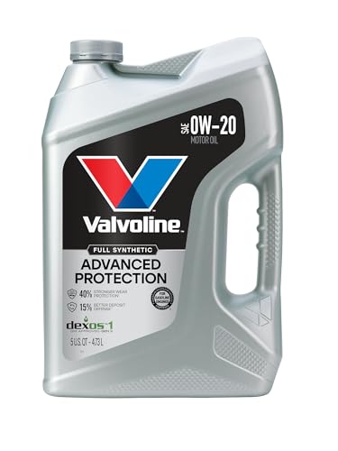
- Advanced protection against the four main causes of engine...
- Delivers 40% stronger wear protection than industry...
- Provides 15% better deposit defense vs. industry standards...
- Up to 2.5X better heat protection vs. industry standards to...
- Engineered for excellent low-temperature flow, reducing...

- Formulated for engines with 75,000 miles or more, Valvoline...
- Delivers 20% better wear protection and 15% better sludge...
- Extra detergents safeguard against friction, corrosion and...
- Advanced friction-fighting additives help maximize...
- Provides performance benefits for high mileage, new and...
Search NHTSA Database for Recalls
Search NHTSA Database for Vehicle Investigations
View Latest Vehicle Investigations
Search NHTSA Database for Vehicle Complaints
View Latest Vehicle Complaints
TSB/Document ID: MC110125
Replacement Service Bulletin Number:
MFR Communication Date: 2026-02-18
MFR Internal Campaign ID/Software Version: 0011600000
Communication Type: Service Campaign
NHTSA Components: ENGINE
MFR Component System:
MFR Component Subsystem:
Previous TSB | Next TSB |
All loosened screw connections have been retightened
correctly.
The fuel system is free of leaks.
The lighting and signal system is functional and the
vehicle is roadworthy.
The brake pads of the front and rear wheel brakes are
resting against the brake disks.
Function test, engine start suppression
Check
Set kill switch to centred position.
Select neutral.
Switch on the ignition.
Neutral indicator light "N" lights up.
Select a gear.
Neutral indicator light "N" goes out.
Press the starter button.
Starter does not operate.
Extend the side stand.
Pull the clutch lever.
Press the starter button.
Starter does not operate.
Retract the side stand.
Press the starter button without releasing the clutch
lever.
Starter operates.
Result
Not all test steps completed successfully.
Measure
Check corresponding components with BMW Motorrad
diagnosis system.
with automated shift assistant OE (022A)
Check
Set kill switch to centred position.
Switch on the ignition.
Neutral position "N" or roll-away protection "P" lights
up.
Neutral position "N" lights up.
Press the starter button.
Starter operates.
Roll-away protection "P" lights up.
Press the starter button.
Starter motor does not run.
Actuate brake and press starter motor button.
Starter operates.
Engine running, gear is engaged.
Extend the side stand.
Engine goes out, roll-away protection "P" lights up.
Engine running, neutral position "N" lights up.
Extend the side stand.
Order No.
14
Gear change not possible.
Result
Not all test steps completed successfully.
Measure
Check corresponding components with BMW Motorrad
diagnosis system.
Order No.
1
0M31 - R 1300 GS Adventure
11 31 097 Removing/installing or replacing timing chain tensioner, right cylinder
Additional work: 46 52 510 Mounting and dismounting the rear-wheel stand with special tools (for motorbikes
without a centre stand)
1
Removing rider’s seat
Actuate seat lock (1).
Disengage rider's seat (2) from spacer buffer (3) and
remove.
With comfort rider's seat OE (077C)
or
with low comfort rider's seat OE (077D)
or
with high comfort rider's seat OE (077E)
Actuate seat lock (1).
Disengage rider's seat (2) from spacer buffer (3) and
remove.
Disconnect connector (4) for seat heating.
Do not twist or put strain on mating connector!
Order No.
2
2
Removing top front-wheel cover
Remove screws (1).
Loosen front-wheel cover (2) out of clip clamps (3) and
hooks (arrows) and pull off to the front.
3
Removing left radiator cowl
Remove screws (1).
Remove radiator cowl (2).
with GS Trophy OE (09T2)
Loosen holder (1) out of exhaust duct (2) (arrow) and
remove.
Order No.
3
4
Removing left fuel-tank cover
Remove screws (1).
Remove tank covers (2).
5
Removing left fairing side panel with
slipstream deflector
Remove screws (1).
Loosen fairing side panel (2) and remove.
6
Removing bottom left tank cover
Remove screw (1).
Loosen cover (2) out of clip clamps (3) and
hook (arrow) and remove.
Order No.
4
7
Removing left exhaust duct
Remove screws (1).
Disconnect connector (1) for additional headlight.
Remove screw (2).
Remove exhaust duct (3).
8
Removing right fuel-tank cover
Remove screws (1).
Remove tank covers (2).
Order No.
5
9
Removing right fairing side panel with slipstream deflector
Remove screws (1).
Loosen fairing side panel (2) and remove.
10
Removing right radiator cowl
Remove screws (1).
Remove radiator cowl (2).
with GS Trophy OE (09T2)
Loosen holder (1) out of exhaust duct (2) (arrow) and
remove.
Order No.
6
11
Removing bottom right tank cover
Remove screw (1).
Loosen cover (2) out of clip clamps (3) and
hook (arrow) and remove.
12
Removing right exhaust duct
Remove cable strap (arrow).
Disconnect connector (1) for air temperature sensor.
Remove cable strap (arrow).
Disconnect connector (1) and loosen from connector
holder (2).
Remove screws (3).
Order No.
7
Disconnect connector (1) for additional headlight.
Remove screws (2).
Remove exhaust duct (3).
13
Removing centre fuel-tank cover
Remove screws (1).
Remove holder (2).
Remove screws (1) and mounts (2).
Loosen tank cover (3) out of clip clamps (4) and remove.
Order No.
8
14
Removing stowage compartment
Remove screws (1) and (2).
Raise storage compartment (3) and disconnect connector (4).
15
Removing fuel tank
Disconnect overflow hose (1).
Disconnect vent hose (2).
Remove cable strap (1).
Disconnect connector (2) for fuel filler cap and loosen.
Loosen line (arrows) and thread out connector.
Order No.
9
Loosen relay holder (1).
Remove screws (1) and (2).
Loosen tank holder (3).
Pull fuel tank (4) slightly to the rear.
Disconnect connector (5) for fuel pump.
WARNING
Fuel is highly flammable and hazardous to health
Risk of fire, risk of damage to health
Comply with the safety regulations.
Disconnect quick-release coupling (6).
Carefully raise lock with screwdriver.
Employ suitable means to catch escaping fuel.
Remove fuel tank (4).
16
Removing right injection valve cover
Remove screws (1).
Remove injection valve cover (2).
Order No.
10
17
Removing right injection valve
Disconnect connector (1) for injection valve.
Remove screw (2).
Loosen injection valve (3).
18
Disengaging expansion tank for coolant
Remove screw (2).
Loosen expansion tank (3) from hooks (arrow).
In doing so, pay attention to hose (1).
19
Disengaging right throttle-valve assembly
Open clamps (1) and (2) using pliers (13 1 512).
Order No.
11
Disconnect connector (1).
Turn throttle valve (2) clockwise outwards until the timing chain tensioner is accessible.
20
Replacing right timing-chain tensioner
Remove timing chain tensioner (1) with piston (2) and
sealing ring (3).
Install new timing chain tensioner (1) with piston (2)
and new sealing ring (3).
Tightening torques
Screw plug for chain tensioner to cylinder
M18 x 1.5
32 Nm
21
Securing right throttle-valve assembly
Connect connector (1).
Turn throttle valve (2) to mounting orientation.
Pay attention to the edge in the rubber sleeve!
Order No.
12
Install clamps (1) and (2) using pliers (13 1 512).
22
Securing expansion tank for coolant
Position expansion tank (3), noting hook (arrow).
Do not kink hose (1).
Install screw (2).
23
Securing right injection valve
Check O-ring (1) for damage; replace O-ring if swollen
or damaged.
Install injection valve (2).
Install screw (3).
Connect connector (4) for injection valve.
Order No.
13
24
Installing right injection-valve cover
Install injection valve cover (2).
Install screws (1).
25
Installing fuel tank
When installing fuel tank (2), note rubber mounts (1),
lines (3) and wiring harness (4).
Position fuel tank (4).
Connect connector (5).
Press fuel pressure line (6) into bush with a little effort.
Press in lock (arrow).
Check pressure line for tight fit.
Position tank holder (3).
Install screws (2) and (1).
Tightening torques
Fuel tank to frame
M8 x 50
19 Nm
Order No.
14
Secure relay holder (1).
Connect overflow hose (1).
Connect vent hose (2).
Route and secure cable (arrows).
Secure and connect connector (2) for the fuel filler cap.
Install cable strap (1).
Order No.
15
26
Installing stowage compartment
Connect connector (4) and position storage compartment (3).
Install screws (1) and (2).
27
Installing centre tank cover
Position tank cover (3) and secure in clip clamps (4).
Install mounts (2) with screws (1).
Position holder (2).
Install screws (1).
Order No.
16
28
Installing right exhaust duct
First connect connector (1) for additional headlight.
Position exhaust duct (3).
Install screws (2).
Install screws (3).
Secure connector (1) on connector holder (2) and connect.
Install cable strap (arrow).
Connect connector (1) for air temperature sensor.
Install cable strap (arrow).
Order No.
17
29
Installing bottom right tank cover
Secure cover (2) in hook (arrow) and clip clamps (3).
Install screw (1).
30
Installing right fairing side panel with
slipstream deflector
Position fairing side panel (2).
Install screws (1).
31
Installing right radiator cowl
with GS Trophy OE (09T2)
Secure holder (1) in exhaust duct (2) (arrow).
Order No.
18
Align radiator cowl (2) and install screws (1).
32
Installing right fuel-tank cover
Position tank cover (2).
Install screws (1).
33
Installing left exhaust duct
First connect connector (1) for additional headlight.
Position exhaust duct (3).
Install screw (2).
Order No.
19
Install screws (1).
34
Installing bottom left tank cover
Secure cover (2) in hook (arrow) and clip clamps (3).
Install screw (1).
35
Installing left fairing side panel with slipstream
deflector
Position fairing side panel (2).
Install screws (1).
Order No.
20
36
Installing left fuel-tank cover
Position tank cover (2).
Install screws (1).

- CEL Doctor: The ANCEL AD310 is one of the best-selling OBD II scanners on the market and is recommended by Scotty Kilmer, a YouTuber and auto mechanic. It can easily determine the cause of the check engine light coming on. After repairing the vehicle's problems, it can quickly read and clear diagnostic trouble codes of emission system, read live data & hard memory data, view freeze frame, I/M monitor readiness and collect vehicle information.
- Sturdy and Compact: Equipped with a 2.5 foot cable made of very thick, flexible insulation. It is important to have a sturdy scanner as it can easily fall to the ground when working in a car. The AD310 OBD2 scanner is a well-constructed mechanic tool with a sleek design. It weighs 12 ounces and measures 8.9 x 6.9 x 1.4 inches. Thanks to its compact design and light weight, transporting the device is not a problem. The buttons are clearly labelled and the screen is large and displays results clearly.
- Accurate Fast and Easy to Use: The AD310 scanner can help you or your mechanic understand if your car is in good condition, provides exceptionally accurate and fast results, reads and clears engine trouble emission codes in seconds after you fixed the problem. This device will let you know immediately and fix the problem right away without any car knowledge. No need for batteries or a charger, get power directly from the OBDII Data Link Connector in your vehicle.
- OBDII Protocols and Car Compatibility: Many cheap scan tools do not really support all OBD2 protocols. AD310 scanner as it can support all OBDII protocols such as KWP2000, J1850 VPW, ISO9141, J1850 PWM and CAN. This device also has extensive vehicle compatibility with 1996 US-based, 2000 EU-based and Asian cars, light trucks, SUVs, as well as newer OBD2 and CAN vehicles both domestic and foreign. Pls confirm with our customer service whether it is compatible with your vehicle before purchasing.
- Home Necessity and Worthy to Own: This is an excellent code reader to travel or home with as it weighs less and it is compact in design. You can easily slide it in your backpack as you head to the garage, or put it on the dashboard, this will be a great fit for you. The AD310 is not only portable, but also accurate and fast in performance. Moreover, it covers various car brands and is suitable for people who just need a code reader to check their car.

- Multi-Functions - Practical Multi-Functions OBD2 code reader features built-in OBD2 DTC lookup library, which help you to determine the cause of the engine light, read code, erase code, view freeze frame, I/M ready, vehicle information, data flow, real-time curve, get vehicle speed information, calculate load value, engine coolant temperature, get engine speed.
- Wide Capability - Supports 9 protocols compatible with most 1996 US-Based, 2000 EU-Based and Asian cars, and newer OBD II & CAN domestic or import vehicles. Supports 6 languages - English,German, Dutch, Spanish, French, Italian.
- 2.8" LCD Display - Designed with a clear display 2.8" Large LCD screen - white backlight and contrast adjustment. No need any battery or charger, OBD reader gets the power directly from your vehicle through the OBDII Data Link Connector.
- Compact Design - Car diagnostic scanner is equipped with a 2.5 feet long cable and made of a very thick flexible insulator.There are 6 buttons on OBD2 Scanner:scroll up/down,enter/exit and buttons that quick query VIN vehicle number& the DTC fault code.
- ABS / Airbag codes NOT Supported - It is able to read and clear check engine information which is part of OBDII system, but it cannot work with non-OBDII systems, including ABS / Airbag / Oil Service Light, etc.

- 【Your Personal CEL Doctor – Read & Clear Engine Codes】The NT301 OBD2 scanner lets you read diagnostic trouble codes (DTCs), check em-issions readiness, turn off your Check Engine Light (CEL) or MIL, reset monitors, and view live data streams. It retrieves your vehicle's VIN instantly. Like all standard OBD2 scanners, it clears codes only after repairs are completed—if the issue persists, the code will return. Designed for DIYers who want to understand what’s really going on under the hood.
- 【Easy Code Reading – Just Plug & Play】Simply plug into the OBD2 port, turn the ignition to “ON” (engine off), and select the correct menu: Select OBDII-> Wait for seconds-> Select Read codes. For accurate results, ensure your vehicle is compatible and the OBD2 port is free from damage or wiring issues. No batteries needed— powered directly by your car.
- 【Live Data Graphing & Accuracy for Most OBD2 Vehicles】View and log live sensor data in graph form—monitor oxygen sensors, fuel trims, coolant temp, RPM, and more. Spot trends and suspicious values in real time. Compatible with most 1996+ gasoline cars, light trucks, and SUVs sold in the U.S., as well as many 2000+ European and Asian models. Also works on 12V diesel vehicles equipped with OBD2.
- 【S-mog Check Helper – Know Your Readiness Status at a Glance】With dedicated I/M readiness hotkeys and a simple Red-Yellow-Green LED indicator, you’ll instantly know if your vehicle is ready for em-issions testing. Built-in speaker provides audio feedback. No guesswork—just confidence before you head to the test center.
- 【A Must-Have Tool for Every Home Mechanic】Compact, rugged, and ready to use right out of the box. The 2.8” color screen is easy to read, even in daylight. No charging or setup required—just plug into the 16-pin DLC and start diagnosing. Recommended by professional mechanics on YouTube and trusted by DIYers worldwide.
Last update on 2026-03-20 / Affiliate links / Images from Amazon Product Advertising API
This product presentation was made with AAWP plugin.