
NHTSA ID Number: 11028485
Manufacturer Communication Number: V0125092080124_3
TSB/Document Date: 2026-02-06
Summary
Software Version Management
If the PDF is very large, it may not load in the preview below.
Some older TSBs had multiple PDFs — visit the NHTSA Website to view all PDFs.
If the TSB PDF does not show, download or view it on the NHTSA Website.
Click on the (+) Plus Sign
Then Click on Associated Document(s)
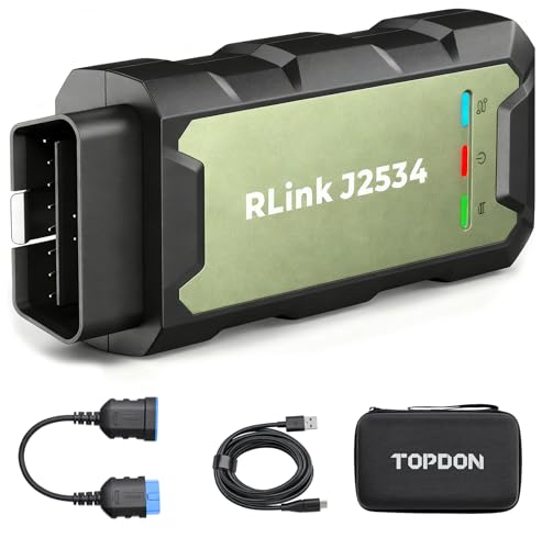
- Advanced VCI Box, Industry-leading J2534 Pass-Thru...
- High-Speed OEM-Level Diagnostics & Programming: Unlock true...
- Coverage for 17 Car Brands & Ultra Reliability: Works...
- User-Friendly RLink Platform & Expert Support: TOPDON’s...
- 6.6 ft USB-C Cable & Portable Storage Case: The RLink J...
Search NHTSA Database for Recalls
Search NHTSA Database for Vehicle Investigations
View Latest Vehicle Investigations
Search NHTSA Database for Vehicle Complaints
View Latest Vehicle Complaints
TSB/Document ID: V0125092080124_3
Replacement Service Bulletin Number:
MFR Communication Date: 2026-01-05
MFR Internal Campaign ID/Software Version: ID.S 5.43KD
Communication Type: Service Bulletin/Repair Instructions
NHTSA Components: UNKNOWN OR OTHER
MFR Component System:
MFR Component Subsystem:
Previous TSB | Next TSB |
Connection offline
Transaction No.: 2080124
Technical Service Bulletin
/3
01-25-09 - Service information, ID. Software (ID.S) Baseline Update ID.S 5.4.3
KD
Condition
Applicable Vehicles
Model(s)
Year
Eng. Code
Trans. Code
VIN Range
From
VIN Range
To
PR Code
ID.4
2024 – 2025
All
All
All
All
V7B, V7C,
V7G
Revision Table
•
Instance Number
Published Date
Version Number
Reason For Update
2080124/3
1/5/2025
01-25-09
Update incorrect
sequence (version)
number
2080124/1
12/18/2025
01-25-07
Original publication.
A customer concern addressed by a technical bulletin leads to this technical bulletin to perform the ID.
S 5.4.3KD update as a solution.
or
•
A technical bulletin and/or parts catalog notice leads to this technical bulletin to perform the ID.S 5.4.3
KD update to maintain compatibility of the vehicle ID.S version with the new part.
CAUTION
If the ID.S 5.4.3KD update is completed, it is technically impossible to perform the update again.
– If campaign 91VH or 917K is applicable and CLOSED, the ID.S 5.4.3KD update was already
completed.
– If campaign 91VH or 917K is applicable and OPEN, perform the ID.S 5.4.3KD update under the
campaign.
– If neither 91VH nor 917K is applicable, then the update for applicable vehicles can be performed using
the instructions given in this technical bulletin.
Technical Background
Not applicable.
Production Solution
Not applicable.
Service
NOTICE
The following points must be observed before and during the update:
– The ODIS tester must be updated to the latest version. See: Elsa2Go > Infomedia > Current ODIS
Service Version.
– The ignition and the radio/ navigation device must be switched on.
– Make sure that a suitable 12V battery charger (VAS 5908 or equivalent with 100 Amp capability) is
connected to support the 12V battery.
– During the software update switch off all unnecessary electric consumers (for example ventilation, seat
heater, lights and so on).
– Make sure that during the software update no electro-magnetic radiation sources (for example, mobile
phones or cordless phones) are used in or near the vehicle.
– To ensure the highest transmission stability for software update of control units only USB hardwire
connection of the diagnosis interface -VAS 6154B or VAS6154A- is allowed. A WiFi connection can
lead to a failure of the software update.
– The driver’s door must remain open during the software update.
– The vehicle must remain in park (gear position “P”) during the software update.
– Place one vehicle key on the reader coil (flatly in the center console cupholder).
1. Document the technical bulletin requiring this update
2. Review prerequisites and perform preliminary work
3. Perform 12V battery check
4. Document vehicle settings
5. Update information electronics (ICAS3)
5.1 Prepare USB stick for the software update of the infotainment system
5.2. Update infotainment system
6. Read 12V battery data
7. Perform software compound update
7.1 Perform software update part 1 (S4210F543)
7.2 ICAS1 factory reset
7.3 Perform software update part 2 (F543)
8. Perform function restore (FES)
9. Perform VKMS adaptation
10. Adapt 12V battery
11. Complete GFF tests in test plan list
12. Test drive vehicle
13. Perform bus sleep
14. End the diagnostic session
15. Restore customer settings
16. Software table
17. Support
CAUTION
Radiator Fan(s) may cycle ON high speed during the Update Process! There is a serious risk that
personal injury may result if contact is made with spinning fan blades.
– Keep hands and all objects away from Radiator Fan(s) during Update Process!
CAUTION
The rear wiper may activate during the software update.
– Ensure that the rear window is free of any obstructions.
CAUTION
Make sure to switch to gear P when working on the vehicle. When working on the vehicle (for example,
when updating software or replacing control units) the vehicle functions may be influenced until the work is
fully completed. This can, for example, mean that the vehicle may not secure itself against rolling if it is left
unattended:
– Therefore, the vehicle must always be parked in P.
– Also actively check before and after faults, breaks or work interruptions that P is selected.
– If a vehicle with rolling capability is needed as part of the work, make absolutely sure that an active
gear is not selected – instead shift to N.
NOTICE
If the customer is enrolled in Car-Net and they have the myVW app downloaded on their phone, they may
receive several notifications during the update process.
1. Document the technical bulletin requiring this update
•
Clearly note on the repair order the technical bulletin number that directed to perform this software
update.
2. Review prerequisites and perform preliminary work
•
•
Prepare the VAS 6150X diagnostic tester (ODIS tester) for use:
‒
Check that the ODIS tester is updated to the latest version. See: Elsa2Go > Infomedia > Current
ODIS Service Version
‒
Ensure the ODIS tester remains powered from its AC power supply adapter for the duration of
the software update. The ODIS tester must not be operated from its internal battery power only.
The tester will shut down when battery power is low, which could result in control unit damage.
‒
Verify that ODIS tester screen saver and power saving settings must remain off. Failure to do so
may result in the tester entering power save mode during the software update, which could result
in control unit damage.
‒
Use only a USB hardwire connection between the VAS 6154A or VAS 6154B diagnostic
interface and the ODIS tester. Performing a software update using a Bluetooth or WiFi
connection to the diagnostic interface increases the risk of a lost connection, which could result
in control unit damage. It also increases the time required to perform the update. Requests for
additional labor time or coverage of a damaged control unit will be denied if the GFF log shows
the update was performed using a Bluetooth or WiFi connection to the diagnostic interface.
Prepare the 12V battery charger VAS 5908 for use:
‒
Before starting programming, it is essential to perform the following actions for the VAS 5908
battery charger. By default, the charger will switch-off automatically after a period of time. To
prevent this, the following must be carried out: Switch it OFF and then ON again each time the
charger is connected. The battery charger’s display must have switched off before it’s restarted.
The charging time can be changed in the charger’s settings menu (access code = 6161). Refer
to the owner’s manual for further information. Do not change any other settings that may damage
the charger or the vehicle.
‒
When connecting the charger to the battery, connect the positive cable to the positive charging
terminal for the battery and connect the negative cable to the grounding lug on the vehicle body.
Never connect the ground cable directly to the negative terminal of the 12V battery.
‒
The 12V battery charger VAS 5908 must remain connected and powered-on for the duration of
the software update, so that the 12V battery remains above 12.5 volts for the duration of the
software update. Failure to do so may cause the update to fail, which could result in control unit
damage.
•
Before starting the software update, ensure the following conditions are met:
‒
The Windows operating system power options must be set according to the ODIS tester setup
directions. See: Elsa2Go > Infomedia > Service references > VHW-22-13 Change Power
Options in Windows® 10 (or latest communication). The “Device Power Management” sections
from the VAS 6150X Diagnostic Laptop – Unpacking and Setup Instructions can also be
referenced.
‒
The dealership’s D3 Edge Box must be installed and configured correctly. See: Elsa2Go >
Infomedia > Service references > D3 Edge Box server Installation and Troubleshooting Guide;
D3 Edgebox User Guide; VHW-25-04 D3 Edgebox Host Name Requirements; VHW-25-03
Revised D3 Edgebox Firewall Requirements – Outbound; VOS-25-70 Most Common Reasons a
D3 Edgebox Isn’t Working; and VOS-25-52 D3 Edgebox Hardware Operation.
‒
The ODIS settings must allow for sending feedback support requests. See: Elsa2Go > Infomedia
> Service references > VOS-25-51 New ODIS Support Feedback Procedure and VOS-25-57
ODIS Support Feedback Important Details (or latest communication).
‒
The ODIS user must have access to Group Retail Portal (GRP). See: Elsa2Go > Infomedia >
Service references > VOS-24-35 ODIS log in Procedure for Group Retail Portal (GRP) and VOS25-78 Group Retail Portal GRP FAQs (or latest communication).
‒
The dealership’s internet firewall settings must meet the specified requirements. See: Elsa2Go >
Infomedia > Service references > VHW-25-02 VAS Diagnostic Device Firewall Settings and
VHW-25-03 Revised D3 Edgebox Firewall Requirements – Outbound (or latest communication).
‒
The ODIS tester must have port 8080 enabled for incoming TCP connections. Please contact
your local IT administrator as needed. If there are any support-related queries, please contact
ODIS service support. The relevant firewall settings can be found in the table below. See:
Elsa2Go > Infomedia > Service references > VHW-25-02 VAS Diagnostic Device Firewall
Settings and VHW-25-03 Revised D3 Edgebox Firewall Requirements – Outbound (or latest
communication).
Configuration:
Communication between ODIS service and TCP port 8080
Direction:
Inbound
Firewall profile:
Private network
Program path to be
released:
All programs
Protocols & ports:
TCP/Local port/8080
Local IP address:
Any IP address
Remote IP address:
192.168.13.69, 192.168.13.100-192.168.13.254
•
Verify that only one vehicle key is present in the vehicle for the duration of the software update.
‒
The vehicle key battery must be OK before starting the software update.
‒
Any additional keys must be a minimum of 20 meters away from the vehicle.
•
Verify the vehicle is not connected to an HV battery charge station for the duration of the software
update.
•
Check for any pre-existing vehicle faults:
•
‒
Any diagnostic trouble codes (DTCs) that specifically indicate “control unit faulty” must be
resolved before starting the software update. Otherwise, the update may stop at the affected
control unit and fail to proceed.
‒
Diagnosis and repair of pre-existing conditions are not covered under this technical bulletin.
If the work steps must be interrupted for any reason, stop at one of the bus-sleep steps.
3. Perform 12V battery check
Perform the 12V battery check using GFF as follows:
•
In the “Test plan” tab, press the “Select self-test” button
•
Select “Service work”
•
Select “Checks on 12V system”
•
Select “Perform 12V battery check” and attach to test plan
•
In the “Test plan” tab, start the “Perform 12V battery check” test program with the “Perform test” button.
•
Follow the instructions in the test program:
‒
If the test result “12V battery is OK” is returned, continue with “4. Document vehicle settings”.
‒
If the test result “12V battery is faulty – replace!” is returned, the 12V battery must be replaced.
Note, if necessary, replacement of the 12V battery is outside the scope of this technical bulletin.
‒
Then continue with "4. Document vehicle settings”. Note, the battery adaptation does not take
place until “10. Adapt 12V battery”.
4. Document vehicle settings
A “factory reset” of the ICAS1 is necessary during the update. This resets the customer settings and vehicle
settings.
NOTICE
To ensure the software compound update does not cause customer dissatisfaction or customer
complaints, the vehicle settings must be documented at this point (photographed) and restored under “15.
Restore customer settings”.
Select and document the vehicle settings in the infotainment system under the “Settings” tile (recommended
via photos).
Then continue with “5. Update information electronics (ICAS3)”.
5. Update information electronics (ICAS3)
In the measure described below the information electronics (ICAS3/diagnostic addresses 005F and 8125) is
updated to SW3748.
The information electronics (ICAS3/diagnostic addresses 005F and 8125) must be updated as follows.
5.1 Prepare USB stick for the software update of the infotainment system
The software must be downloaded via the Flash Media Creator (FMC). See: Elsa2Go > Infomedia > Service
references > VOS-25-58 Flash Media Creator (FMC) for D3 Edgebox (Replaces SD Creator)
•
•
A commercially available USB stick is required. The USB stick is servicing material, and the cost of the
USB stick will not be reimbursed. The USB stick can be reused for multiple software updates.
‒
Use only a 32GB stick for this update – a USB stick of higher capacity cannot be used.
‒
The vehicle infotainment uses a USB-C connector. If the software is downloaded onto a USB-A
stick, a single device USB-C adapter will be required (a USB hub is not allowed).
‒
USB type C (at least USB 2.0), reading/writing speed: at least 40 MB/s / 10 MB/s.
‒
USB type A including type C (at least USB 2.0), reading/writing speed: at least 40 MB/s / 10 MB
/s.
‒
USB type A with adapter to USB type C possible (at least USB 2.0), reading/writing speed: at
least 40 MB/s / 10 MB/s.
Before it is used, label the USB stick with the respective part number from the following table:
ID.S version
Software part number to create USB stick
5.4.3KD
3G8.919.360.DC
NOTICE
If the search for the software part number returns no result, check if the certificate is valid.
– In the FMC software settings, select the valid certificate used with ODIS.
NOTICE
As a best practice, the USB drive should be recreated on a regular basis from the Flash Media Creator
(FMC) to avoid file corruption which can lead to USB update errors.
– Do not use files saved locally to the PC or copy a USB stick that you have made. Only use the Flash
Media Creator (FMC) to make the USB stick. The Flash Media Creator (FMC) checks whether the USB
stick is correct. Software updates with a copied USB stick can damage the device if the software
update is interrupted. Any device damaged by an interrupted software update caused by an improperly
made USB stick cannot be claimed under warranty.
– Do not use a USB hub (USB distributor to use several USB devices on one USB port) to install the
software update.
5.2. Update infotainment system
•
Remove any USB devices, charging cables, etc. from the USB ports.
•
If connected, remove the diagnostic interface from the vehicle OBD port.
•
Place one key flatly on the reader coil (see figure 1).
Figure 1: Reader coil
NOTICE
The following points must be observed before and during the update:
– The ODIS tester must be updated to the latest version. See: Elsa2Go > Infomedia > Current ODIS
Service Version.
– The ignition and the radio/ navigation device must be switched on.
– Make sure that a suitable 12V battery charger (VAS 5908 or equivalent with 100 Amp capability) is
connected to support the 12V battery.
– During the software update switch off all unnecessary electric consumers (for example ventilation, seat
heater, lights and so on).
– Make sure that during the software update no electro-magnetic radiation sources (for example, mobile
phones or cordless phones) are used in or near the vehicle.
– To ensure the highest transmission stability for software update of control units only USB hardwire
connection of the diagnosis interface -VAS 6154B or VAS6154A- is allowed. A WiFi connection can
lead to a failure of the software update.
– The driver’s door must remain open during the software update.
– The vehicle must remain in park (gear position “P”) during the software update.
– Place one vehicle key on the reader coil (flatly in the center console cupholder).
•
Switch on the ignition.
•
Switch on infotainment system and wait 1 minute until the device has completely started.
•
Insert the USB stick into USB port 1 or 2 in the center console (see figure 2).
Figure 2: USB stick
•
Hold the home button until the “Service mode” opens (see figure 3).
Figure 3: Home button
•
Select "Software update/versions” (see figure 4).
Figure 4: Software update/versions
•
Start the software update with the “Start” button (see figure 5).
Figure 5: Start button
•
Select "Update” (see figure 6).
Figure 6: Update button
•
Select “USB 1” or “USB 2”, depending on into which port the USB stick was previously inserted (see
figure 7).
Figure 7: USB port selection
•
Page 1 of the application to be updated is shown, press “Next list” button.
•
Page 2 of the application to be updated is shown, press "Start update" (see figure 8).
Figure 8: Start update
•
The message "Update must not be cancelled under any circumstances” is shown.
•
Press “Start update” (see figure 9).
Figure 9: Start update
NOTICE
If the part number and software version are already current, the automatic update routine may proceed
quickly and perform verification only.
•
The individual applications are first copied, then updated and verified. The progress is shown on the
right next to each application in percent (see figure 10).
Figure 10: Update progress
•
After updating the applications are restarted.
•
If the result display “OK” is shown after every application (see figure 11), continue by pressing
“Resume” (see figure 11). If “n.OK” appears after one or several applications, the update must be
repeated by pressing “Retry” (see figure 11).
Figure 11: Resume button
•
After installation is complete a confirmation message appears (see figure 12).
Figure 12: Installation complete
•
Via the “Setup” button -> info -> system information, the “device part number” and the “software” (see
figure 13) can be used to compare successful software update with the software table (see 16.
Software table).
Figure 13: Part number and software
•
After the update the USB stick can be removed.
NOTICE
If the part number and/or the software version are incorrectly shown, one of the following measures can
help:
– Long-press reset: Hold the on/off button until the infotainment system restarts.
– Hard reset: Remove fuse SC30 for one minute and reinsert.
– Repeat update: Reformat the USB stick and download the correct device software again (if possible:
use a different USB stick).
•
Connect the ODIS tester and manually identify the diagnostic addresses 005F and 8125 so that the
new control unit identification after the update via the USB stick is able to be sent online when
necessary in later steps. Then continue with “6. Read 12V battery adaptation.”

- CEL Doctor: The ANCEL AD310 is one of the best-selling OBD II scanners on the market and is recommended by Scotty Kilmer, a YouTuber and auto mechanic. It can easily determine the cause of the check engine light coming on. After repairing the vehicle's problems, it can quickly read and clear diagnostic trouble codes of emission system, read live data & hard memory data, view freeze frame, I/M monitor readiness and collect vehicle information.
- Sturdy and Compact: Equipped with a 2.5 foot cable made of very thick, flexible insulation. It is important to have a sturdy scanner as it can easily fall to the ground when working in a car. The AD310 OBD2 scanner is a well-constructed mechanic tool with a sleek design. It weighs 12 ounces and measures 8.9 x 6.9 x 1.4 inches. Thanks to its compact design and light weight, transporting the device is not a problem. The buttons are clearly labelled and the screen is large and displays results clearly.
- Accurate Fast and Easy to Use: The AD310 scanner can help you or your mechanic understand if your car is in good condition, provides exceptionally accurate and fast results, reads and clears engine trouble emission codes in seconds after you fixed the problem. This device will let you know immediately and fix the problem right away without any car knowledge. No need for batteries or a charger, get power directly from the OBDII Data Link Connector in your vehicle.
- OBDII Protocols and Car Compatibility: Many cheap scan tools do not really support all OBD2 protocols. AD310 scanner as it can support all OBDII protocols such as KWP2000, J1850 VPW, ISO9141, J1850 PWM and CAN. This device also has extensive vehicle compatibility with 1996 US-based, 2000 EU-based and Asian cars, light trucks, SUVs, as well as newer OBD2 and CAN vehicles both domestic and foreign. Pls confirm with our customer service whether it is compatible with your vehicle before purchasing.
- Home Necessity and Worthy to Own: This is an excellent code reader to travel or home with as it weighs less and it is compact in design. You can easily slide it in your backpack as you head to the garage, or put it on the dashboard, this will be a great fit for you. The AD310 is not only portable, but also accurate and fast in performance. Moreover, it covers various car brands and is suitable for people who just need a code reader to check their car.

- Multi-Functions - Practical Multi-Functions OBD2 code reader features built-in OBD2 DTC lookup library, which help you to determine the cause of the engine light, read code, erase code, view freeze frame, I/M ready, vehicle information, data flow, real-time curve, get vehicle speed information, calculate load value, engine coolant temperature, get engine speed.
- Wide Capability - Supports 9 protocols compatible with most 1996 US-Based, 2000 EU-Based and Asian cars, and newer OBD II & CAN domestic or import vehicles. Supports 6 languages - English,German, Dutch, Spanish, French, Italian.
- 2.8" LCD Display - Designed with a clear display 2.8" Large LCD screen - white backlight and contrast adjustment. No need any battery or charger, OBD reader gets the power directly from your vehicle through the OBDII Data Link Connector.
- Compact Design - Car diagnostic scanner is equipped with a 2.5 feet long cable and made of a very thick flexible insulator.There are 6 buttons on OBD2 Scanner:scroll up/down,enter/exit and buttons that quick query VIN vehicle number& the DTC fault code.
- ABS / Airbag codes NOT Supported - It is able to read and clear check engine information which is part of OBDII system, but it cannot work with non-OBDII systems, including ABS / Airbag / Oil Service Light, etc.

- 【Your Personal CEL Doctor – Read & Clear Engine Codes】The NT301 OBD2 scanner lets you read diagnostic trouble codes (DTCs), check em-issions readiness, turn off your Check Engine Light (CEL) or MIL, reset monitors, and view live data streams. It retrieves your vehicle's VIN instantly. Like all standard OBD2 scanners, it clears codes only after repairs are completed—if the issue persists, the code will return. Designed for DIYers who want to understand what’s really going on under the hood.
- 【Easy Code Reading – Just Plug & Play】Simply plug into the OBD2 port, turn the ignition to “ON” (engine off), and select the correct menu: Select OBDII-> Wait for seconds-> Select Read codes. For accurate results, ensure your vehicle is compatible and the OBD2 port is free from damage or wiring issues. No batteries needed— powered directly by your car.
- 【Live Data Graphing & Accuracy for Most OBD2 Vehicles】View and log live sensor data in graph form—monitor oxygen sensors, fuel trims, coolant temp, RPM, and more. Spot trends and suspicious values in real time. Compatible with most 1996+ gasoline cars, light trucks, and SUVs sold in the U.S., as well as many 2000+ European and Asian models. Also works on 12V diesel vehicles equipped with OBD2.
- 【S-mog Check Helper – Know Your Readiness Status at a Glance】With dedicated I/M readiness hotkeys and a simple Red-Yellow-Green LED indicator, you’ll instantly know if your vehicle is ready for em-issions testing. Built-in speaker provides audio feedback. No guesswork—just confidence before you head to the test center.
- 【A Must-Have Tool for Every Home Mechanic】Compact, rugged, and ready to use right out of the box. The 2.8” color screen is easy to read, even in daylight. No charging or setup required—just plug into the 16-pin DLC and start diagnosing. Recommended by professional mechanics on YouTube and trusted by DIYers worldwide.
Last update on 2026-03-23 / Affiliate links / Images from Amazon Product Advertising API
This product presentation was made with AAWP plugin.