
NHTSA ID Number: 11027245
Manufacturer Communication Number: Circular 91VH_20251202
TSB/Document Date: 2026-01-07
Summary
Vehicle Software (SW Level 5.4.3) - Updated test plan steps and added additional test plan photos. Updated bus sleep note in claiming section.
If the PDF is very large, it may not load in the preview below.
Some older TSBs had multiple PDFs — visit the NHTSA Website to view all PDFs.
If the TSB PDF does not show, download or view it on the NHTSA Website.
Click on the (+) Plus Sign
Then Click on Associated Document(s)
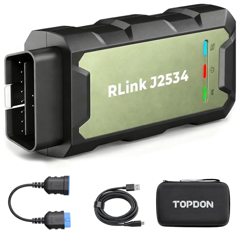
- Advanced VCI Box, Industry-leading J2534 Pass-Thru...
- High-Speed OEM-Level Diagnostics & Programming: Unlock true...
- Coverage for 17 Car Brands & Ultra Reliability: Works...
- User-Friendly RLink Platform & Expert Support: TOPDON’s...
- 6.6 ft USB-C Cable & Portable Storage Case: The RLink J...
Search NHTSA Database for Recalls
Search NHTSA Database for Vehicle Investigations
View Latest Vehicle Investigations
Search NHTSA Database for Vehicle Complaints
View Latest Vehicle Complaints
TSB/Document ID: Circular 91VH_20251202
Replacement Service Bulletin Number:
MFR Communication Date: 2025-12-02
MFR Internal Campaign ID/Software Version: 91VH
Communication Type: Service Campaign
NHTSA Components: UNKNOWN OR OTHER
MFR Component System:
MFR Component Subsystem:
Previous TSB | Next TSB |
electric window lifters might be lost.
•
•
Perform manual basic settings of steering angle sender -G85-:
o
Create drive readiness.
o
Turn steering wheel completely to the left and hold in the end position for 3 seconds.
o
Turn steering wheel completely to the right and hold in the end position for 3 seconds.
o
Return steering wheel to straight-ahead position.
o
Yellow steering light in cluster should go out.
Adapt end stops (soft stop) of the electric window lifter for all windows:
o
Lower window completely. Release the switch. Hold window switch in the down position, at the
second detent for 3 seconds.
o
Raise window completely. Release the switch. Hold window switch in the up position, at the second
detent for 3 seconds.
NOTE
After completion of the software updates, restore any customer settings that have changed back to what was
previously stored.
Proceed to Step 12 for performing GFF test plans for faults created by the flash process
91VH Page 37 of 46
Step 12 – Perform GFF Test Plans for All Faults Created by the Flash Process
•
Exit Diagnosis and select “Yes” to end the
diagnostic session.
•
When prompted to continue Guided Fault
Finding, select “NO”.
•
GFF will be exited, and faults will be erased.
•
Static faults created by the flash process will
remain.
•
When prompted, select “YES” to populate new
test plans.
91VH Page 38 of 46
•
Work through all test plans for faults created
by the flash process.
•
Reference any applicable TSBs that address
“ghost” faults.
•
Pay close attention to all steps outlined in the
test plans and follow them exactly as
described.
NOTE
Driver assist systems will not require re-calibration
due to this software update.
NOTE
Static faults may store in various control modules
during the flash.
The ID Light may not operate as designed after the
flash.
It may be necessary to perform the following in order
to clear the faults and restore the ID Light operation:
•
Drive the vehicle a short distance (around
the parking lot, for example).
•
Perform a bus sleep.
Proceed to Section C
91VH Page 39 of 46
Section C – Road Test for Three-Phase Drive and Travel Assist Verification
CRITICAL REPAIR STEP
STOP!
Perform a test drive above 20 mph/35 kph to
calibrate the three-phase drive -VX54-.
When performing this road test, the vehicle will
momentarily lose acceleration when the threephase drive -VX54- calibrates. Ensure the road test
is performed in a safe manner.
NOTE
The software flash may result in the loss of
adaptation of the Travel Assist Function. The steps
below must be performed after completion of the
flash.
•
Prior to performing the road test, document the
customer cruise control settings in the instrument
cluster using the buttons on the steering wheel.
•
Switch to “ACC” mode.
•
Once ACC mode is selected, perform the road test
to calibrate the 3-phase motor.
•
After the 3-phase motor calibration is completed,
press the “Set” button to activate the ACC system.
•
Once the ACC system is activated, the procedure
is complete.
•
Return the cruise control settings back to the
previous customer settings.
91VH Page 40 of 46
Perform Bus Sleep Procedure:
•
Carry out the following steps in the specified sequence to put the vehicle in a bus sleep.
•
Switch off the ignition.
•
Remove diagnosis interface from the vehicle diagnosis connection.
•
Remove battery charger from the 12V battery.
•
Close front and rear lid as well as all doors.
•
Lock vehicle.
•
Move vehicle key (remote control) at least 20 meters away from the vehicle.
•
Wait at least 15 minutes until the vehicle is in bus silence.
•
Then unlock vehicle again.
•
Connect and switch on battery charger.
•
Insert diagnosis interface on vehicle diagnosis connection.
•
Switch on the ignition.
•
Place a vehicle key (remote control) in the cup holder area on the reader coil.
•
Exit GFF and send diagnostic protocol online.
Restore Customer Settings:
•
Restore the customer vehicle settings using the previously recorded information.
Proceed to Section D
91VH Page 41 of 46
Section D – Campaign Completion Label
•
Fill out and affix Campaign Completion Label,
part number CAMP 010 000, next to the vehicle
emission control information label.
TIP
Ensure Campaign Completion Label does not cover
any existing label(s).
91VH Page 42 of 46
Appendix A – Flash Errors and Possible Solutions
IMPORTANT
The recovery steps in the tables below may have to be performed multiple times throughout the flash process.
If the information provided in Appendix A does not resolve the concern, please create a TAC WEB ticket for
further direction before performing any more flash attempts.
•
Example #1: Error “A” is received for a control module when the first SVM is performed. The recovery steps
for error “A” corrected the issue and the first SVM completed successfully. The same error is received when
performing the second SVM. The recovery steps listed for error “A” should be utilized again.
•
Example #2: Error “B” is received for a control module when attempting the first SVM. It has been verified
that the correct diagnostic equipment specified in this circular is being used. The recovery steps are not
working. The recovery steps have been attempted two times, but error “B” is still occurring during the first
SVM for the same control module. A TAC case MUST be created prior to performing the SVM again.
•
Example #3: Error “C” is received for a control module when performing the first SVM code. The recovery
steps are performed and the first SVM continues past this error. Towards the end of the end of the first SVM,
it fails with error “D” for different control module. The recovery steps should be utilized for the new error prior
to creating a TAC WEB ticket.
WARNING
Requests for additional GFF time resulting from the scenarios listed below will not be covered by the campaign:
•
SVM codes unnecessarily repeated
•
The recovery steps listed below were not utilized
•
A TAC case was not created after the recovery steps were exhausted
NOTE
Requests for additional parts and/or labor to resolve IT issues or problems in relation to dealer tools will not be
covered under the campaign.
91VH Page 43 of 46
FLASH ERROR INFORMATION
Error
Cause
Possible correction
ERP8113
The measure cannot be
carried out because of SFD
security access/activation.
•
Verify that a VAS 6150 D (or higher) scan tool is being
used.
•
Verify that a VAS USB cable that is in good condition is
being used (no third-party USB cables)
•
Verify that a VAS 6154 A (or higher) diagnostic head is
being used
o Usage of a VAS 6154 (no index) diagnostic head
is prohibited and may result in 8113 errors
•
Perform SFD activation test plan for the following
modules:
o 0009, 0019, 8123, 8124, C002, and 0082
(if equipped)
o Repeat the appropriate SVM
•
ERP0220E
Unknown SVM code
If the error occurs for modules that are not associated
with the modules listed above, DA 0075 for example:
o Perform SFD activation test plan for the affected
module
o Repeat the appropriate SVM
•
Check the SVM codes being entered into the test plan
•
Correct as necessary
•
Repeat the appropriate SVM
ODS5003E
or
ERP0215E
On at least one control unit,
the operating conditions for
the measure are not fulfilled
(for example, incorrect SW
part number/HW part
number/hardware/software)
•
Manually identify the affected control module(s) or start
a new GFF session and repeat the appropriate SVM
•
Perform a bus sleep or reset the control module, then
repeat the appropriate SVM
ERP8067
or
ERP8101
Reference-baseline does
not match any mapping as
actual baseline.
or
SDB responds with
disallowed messages to
DA: XXXX.
•
Ensure that the first SVM code has fully completed prior
to attempting the second SVM code:
o This can be done by reviewing the completion
list in the test plan, see page 28
o This can also be done by reviewing the
completion list in the fault log
o Repeat the appropriate SVM
•
If the SVM codes were run out of order, perform the first
SVM code again and note if either error returns
o If these errors DO NOT return, and the first
SVM completes, proceed with the campaign
instructions. A TAC Case is not needed.
o If the errors return, and the SVMs are failing, a
TAC WEB ticket will be required
Continued on next page
91VH Page 44 of 46
Error
Cause
Possible correction
ERP8118
or
ERP8075
or
ERP0225E
The measure cannot be
carried out because of
missing control unit data.
Often not all necessary
control units are “identified”
or “reachable”.
•
Attempt to manually identify the affected module
•
If the module can be identified and it is responding
properly:
o Repeat the appropriate SVM
•
•
ERP9024
or
ERP9999
“No vehicle
connected” message
There are connection issues
to the D3 Edge Box that
need to be resolved.
There is a poor connection
between the vehicle and the
scan tool or Terminal 15 did
not switch back on.
If a module cannot be manually identified:
o Switch off ignition
o Send diagnostic protocol online
o Disconnect diagnostic interface from vehicle
o Restart ODIS
o Remove the fuse for the module that had the failure
for 10 seconds
o Reinstall the fuse
o Perform a bus sleep
o Start a NEW GFF session
o Identify the module
o Repeat the appropriate SVM
If this does not correct the issue:
o A terminal 30 reset (capacitive discharge) MUST
be performed
o Refer to Appendix B for instructions on how to
properly perform a capacitive discharge on an ID.4
o Restart the Scan tool
o Start a NEW GFF session
o Identify the affected module
o Repeat the appropriate SVM
•
Contact IT support in order to check the URL
configuration and software version of your D³
infrastructure
•
Ensure that the scan tool firewall and port settings are
configured per VHW-24-10
•
Repeat the appropriate SVM after the IT issue has
been resolved
•
Cycle the ignition back on
•
Check the USB connections at the diagnostic head and
the scan tool
•
Check the USB cable for damage
•
Check for pin fit issues at the DLC
•
Repeat the appropriate SVM after the connection issue
has been resolved
91VH Page 45 of 46
Appendix B – ID.4 Capacitive Discharge Procedure
•
•
•
•
With the key on the reader coil, remove the negative cable from the 12V battery, leaving the positive cable in
place.
o Do not touch the 12V battery positive and negative cables together for any reason!
Press and release the brake pedal briefly.
Verify that the instrument cluster has shut off.
o If the cluster does not turn off, switch the ignition on and press the brake pedal again.
Once the instrument cluster switches off after pressing the brake pedal, leave the vehicle in this state for 2-3
minutes.
•
Once the capacitive discharge has been completed, reconnect the negative battery cable.
•
Continue with the appropriate recovery steps listed in appendix A.
91VH Page 46 of 46

- CEL Doctor: The ANCEL AD310 is one of the best-selling OBD II scanners on the market and is recommended by Scotty Kilmer, a YouTuber and auto mechanic. It can easily determine the cause of the check engine light coming on. After repairing the vehicle's problems, it can quickly read and clear diagnostic trouble codes of emission system, read live data & hard memory data, view freeze frame, I/M monitor readiness and collect vehicle information.
- Sturdy and Compact: Equipped with a 2.5 foot cable made of very thick, flexible insulation. It is important to have a sturdy scanner as it can easily fall to the ground when working in a car. The AD310 OBD2 scanner is a well-constructed mechanic tool with a sleek design. It weighs 12 ounces and measures 8.9 x 6.9 x 1.4 inches. Thanks to its compact design and light weight, transporting the device is not a problem. The buttons are clearly labelled and the screen is large and displays results clearly.
- Accurate Fast and Easy to Use: The AD310 scanner can help you or your mechanic understand if your car is in good condition, provides exceptionally accurate and fast results, reads and clears engine trouble emission codes in seconds after you fixed the problem. This device will let you know immediately and fix the problem right away without any car knowledge. No need for batteries or a charger, get power directly from the OBDII Data Link Connector in your vehicle.
- OBDII Protocols and Car Compatibility: Many cheap scan tools do not really support all OBD2 protocols. AD310 scanner as it can support all OBDII protocols such as KWP2000, J1850 VPW, ISO9141, J1850 PWM and CAN. This device also has extensive vehicle compatibility with 1996 US-based, 2000 EU-based and Asian cars, light trucks, SUVs, as well as newer OBD2 and CAN vehicles both domestic and foreign. Pls confirm with our customer service whether it is compatible with your vehicle before purchasing.
- Home Necessity and Worthy to Own: This is an excellent code reader to travel or home with as it weighs less and it is compact in design. You can easily slide it in your backpack as you head to the garage, or put it on the dashboard, this will be a great fit for you. The AD310 is not only portable, but also accurate and fast in performance. Moreover, it covers various car brands and is suitable for people who just need a code reader to check their car.

- Multi-Functions - Practical Multi-Functions OBD2 code reader features built-in OBD2 DTC lookup library, which help you to determine the cause of the engine light, read code, erase code, view freeze frame, I/M ready, vehicle information, data flow, real-time curve, get vehicle speed information, calculate load value, engine coolant temperature, get engine speed.
- Wide Capability - Supports 9 protocols compatible with most 1996 US-Based, 2000 EU-Based and Asian cars, and newer OBD II & CAN domestic or import vehicles. Supports 6 languages - English,German, Dutch, Spanish, French, Italian.
- 2.8" LCD Display - Designed with a clear display 2.8" Large LCD screen - white backlight and contrast adjustment. No need any battery or charger, OBD reader gets the power directly from your vehicle through the OBDII Data Link Connector.
- Compact Design - Car diagnostic scanner is equipped with a 2.5 feet long cable and made of a very thick flexible insulator.There are 6 buttons on OBD2 Scanner:scroll up/down,enter/exit and buttons that quick query VIN vehicle number& the DTC fault code.
- ABS / Airbag codes NOT Supported - It is able to read and clear check engine information which is part of OBDII system, but it cannot work with non-OBDII systems, including ABS / Airbag / Oil Service Light, etc.

- 【Your Personal CEL Doctor – Read & Clear Engine Codes】The NT301 OBD2 scanner lets you read diagnostic trouble codes (DTCs), check em-issions readiness, turn off your Check Engine Light (CEL) or MIL, reset monitors, and view live data streams. It retrieves your vehicle's VIN instantly. Like all standard OBD2 scanners, it clears codes only after repairs are completed—if the issue persists, the code will return. Designed for DIYers who want to understand what’s really going on under the hood.
- 【Easy Code Reading – Just Plug & Play】Simply plug into the OBD2 port, turn the ignition to “ON” (engine off), and select the correct menu: Select OBDII-> Wait for seconds-> Select Read codes. For accurate results, ensure your vehicle is compatible and the OBD2 port is free from damage or wiring issues. No batteries needed— powered directly by your car.
- 【Live Data Graphing & Accuracy for Most OBD2 Vehicles】View and log live sensor data in graph form—monitor oxygen sensors, fuel trims, coolant temp, RPM, and more. Spot trends and suspicious values in real time. Compatible with most 1996+ gasoline cars, light trucks, and SUVs sold in the U.S., as well as many 2000+ European and Asian models. Also works on 12V diesel vehicles equipped with OBD2.
- 【S-mog Check Helper – Know Your Readiness Status at a Glance】With dedicated I/M readiness hotkeys and a simple Red-Yellow-Green LED indicator, you’ll instantly know if your vehicle is ready for em-issions testing. Built-in speaker provides audio feedback. No guesswork—just confidence before you head to the test center.
- 【A Must-Have Tool for Every Home Mechanic】Compact, rugged, and ready to use right out of the box. The 2.8” color screen is easy to read, even in daylight. No charging or setup required—just plug into the 16-pin DLC and start diagnosing. Recommended by professional mechanics on YouTube and trusted by DIYers worldwide.
Last update on 2026-03-27 / Affiliate links / Images from Amazon Product Advertising API
This product presentation was made with AAWP plugin.