
NHTSA ID Number: 11027967
Manufacturer Communication Number: SD-13-47572A
TSB/Document Date: 2026-02-02
Summary
Bendix® TABS‑6™ Advanced Multi-Channel (MC) (ABS/TRSP) and MC LITE (ABS Only) Trailer Antilock Braking System (ABS) Modules The Bendix® TABS‑6™ Advanced (ADV) Multi-Channel (MC) module (Generation 2) is an integrated, MC (4S/2M) trailer service brake module controller for air-braked, heavy-duty semi trailers that features the Bendix® Antilock Brake System (ABS) and Bendix® Trailer Roll Stability Program (TRSP®). TABS-6 ADV MC offers a LITE version, which provides an ABS-only functionality while keeping the benefits of having a multi-channel system. NOTE: All references to the TABS-6 module in this document – aside from TRSP-related references – also include the MC LITE module. Installed on semi-trailers, the module acts as a relay valve during service braking, but during ABS events, it may intervene to help maintain vehicle stability by modulating brake pressure at the wheel ends. The Bendix TRSP monitors the trailer's motion and reduces the risk of rollovers by automatically applying the brakes when a risk of a rollover is detected. NOTE: The Bendix TRSP is not available for TABS-6 MC LITE.
If the PDF is very large, it may not load in the preview below.
Some older TSBs had multiple PDFs — visit the NHTSA Website to view all PDFs.
If the TSB PDF does not show, download or view it on the NHTSA Website.
Click on the (+) Plus Sign
Then Click on Associated Document(s)
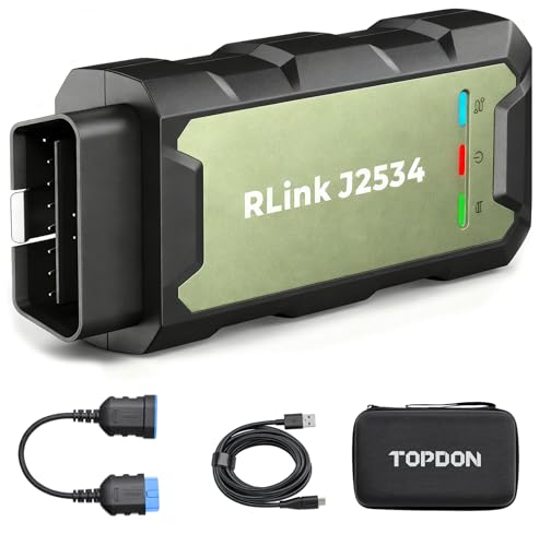
- Advanced VCI Box, Industry-leading J2534 Pass-Thru...
- High-Speed OEM-Level Diagnostics & Programming: Unlock true...
- Coverage for 17 Car Brands & Ultra Reliability: Works...
- User-Friendly RLink Platform & Expert Support: TOPDON’s...
- 6.6 ft USB-C Cable & Portable Storage Case: The RLink J...
Search NHTSA Database for Recalls
Search NHTSA Database for Vehicle Investigations
View Latest Vehicle Investigations
Search NHTSA Database for Vehicle Complaints
View Latest Vehicle Complaints
TSB/Document ID: SD-13-47572A
Replacement Service Bulletin Number:
MFR Communication Date: 2026-01-31
MFR Internal Campaign ID/Software Version:
Communication Type: Service Bulletin/Repair Instructions
NHTSA Components: SERVICE BRAKES
MFR Component System: Trailer
MFR Component Subsystem: ABS
Previous TSB | Next TSB |
Degrees of Vertical
2. R
econnect all of the air hoses and plugs to the module.
Depending on the installation, additional plugs may
be necessary. Thread sealant products that contain
PTFE may be used; however, thread sealant tape is not
recommended as there is a potential for tape material
entering the valve and affecting the valve’s operation.
Ensure no thread sealant enters the valve. All air hoses
and fittings should be checked for leaks prior to returning
the vehicle to service.
Driving
Direction
Figure 16 – Installation on the Trailer (Longitudinal)
40" m)
(1 m)
from
mid-pointbetween
between the
100 in. ±(2.5
from
midpoint
theaxles
axles
10°
10°
Frame-Mount Module: The TABS‑6 ADV MC module uses
three (3) Class-8 steel M10x1.5 lock nuts with washers,
torqued to 354 ± 44.4 in.-lbs (40±5 N•m).
+ 2(5in.cm)
± 2"
(5.08center
cm)
from
from
center
of trailer
3. R
econnect the ECU power, auxiliary power (if present),
and WSS electrical connectors to the ECU. Apply a small
amount of non-conductive electrical grease to each
connector pin before reconnecting.
NOTE: The WSS must follow the orientation of the module
as shown in Figure 18 for fixed-axle trailers. Where a lift
axle is present, and sensors are to be installed on that
axle, secondary sensors “SE” and “SF” must be used
for the lift axle.
•
It is necessary to fix the WSS to the orientation of
the lateral acceleration sensor for plausibility checks
between the sensors.
•
If the WSS location does not match the orientation
of the TABS‑6 ADV MC module shown in Figure 18,
a DTC will be generated and the ABS indicator lamp
will be illuminated.
•
efer to the raised lettering on the casting body,
R
or see Figure 18, for WSS locations, “S-C,” “S-D,”
“S-E,” and “S-F.”
of trailer
The TABS‑6 ADV MC or MC LITE module must be located no more than
40 inches from the mid-point between the axles, and within two inches
from the center line of the trailer (for TRSP variants, if there is an offset
from the centerline, it should be configured on the ECU).
Figure 17 – Installation on the Trailer (Center Line)
4. L
eakage and operational tests must be performed before
returning the vehicle to service.
20
Right - “Curb-Side”
Sensor
“S-F”
Right - “Curb-Side”
Sensor
“S-D”
P21
Driving
Direction
Sensor
“S-C”
Driving
Sensor
“S-C”
Left - “Road-Side”
P22
Direction
P22
Sensor
“S-E”
Sensor
“S-E”
P21
Sensor
“S-D”
Sensor
“S-F”
Left - “Road-Side”
Figure 18 – WSS Locations
21
LEAKAGE AND OPERATIONAL TESTS
For NPTF fittings, the use of a thread sealant is
recommended. This can be a pre-applied or a handapplied sealant product (with PTFE). When using a
hand-applied sealant, use caution so as not to over-apply.
Always follow the fitting manufacturer’s pre-applied or
hand-applied thread sealant recommendations. Use of
PTFE tape is not approved and will void the Bendix ABS
and the Bendix TRSP valve warranty.
1. Before performing the leakage tests, block the wheels.
2. Fully charge the ABS and verify proper brake adjustment.
3. M
ake several trailer brake applications and check for
prompt application and release at each wheel.
4. Perform the leak-down test procedure:
•
et up the pressure circuits to apply supply (red)
S
line and service pressures with a regulator and a
pressure gauge on each line.
•
pply 110 - 120 psi to the trailer supply (red) circuit
A
to release the parking brake.
•
Apply the service brakes at 90 - 95 psi.
•
Identify and record the pressure from the gauge on
the supply (red) line and the service line.
•
•
22
ut off the pressure to the supply (red) line before
C
the pressure gauge and monitor for the pressure to
drop. If the pressure drops less than 3 psi in one
(1) minute, the supply (red) line test passes. If the
pressure drops more than 3 psi in one (1) minute,
identify and correct the source of the leak on the
supply (red) line.
If the supply (red) line test passes, repeat the test
for the service line. If the pressure drops less than 2
psi in one (1) minute, the test passes. If the pressure
drops more than 2 psi in one (1) minute, identify and
correct the source of the leak on the service line.
•
soap and water solution can be used to identify
A
sources of leaks on the fittings and valves.
•
If available, a Lite-Check® machine can be used to
perform the leak-down test.
5. A
pply power and monitor the power-up sequence to verify
proper system operation.
6. C
alibrate and set the odometer parameters, if necessary,
using a diagnostic tool.
7. R
efer to Appendix A and record all applicable information
prior to programming the TABS-6 ADV MC or MC LITE
module.
8. P
erform an installation test using ACOM DIAGNOSTIC
SOFTWARE. Minimum tests that are required to verify
the proper installation of the ABS/TRSP system are:
•
ECU Information: This test provides the user with
specific ECU information. It is required that no
Diagnostic Trouble Codes (DTCs) (other than “endof-line test not completed”) are present and that the
ECU has been configured.
•
Wheel End Sequence Test: During this test, checks
are carried out that verify the correlation of the wheel
installed with a WSS and the pressure modulator that
controls the pressure to the associated brake.
•
Lateral Acceleration Test: The installation angle
information is retrieved from the ECU and compared
to the predefined limits (± 5°). This test verifies the
unit is installed as close to horizontal as possible.
NOTE: TABS-6 MC LITE does not support lateral
acceleration, but should still follow TABS-6 ADV MC
installation instructions and recommendations.
•
Pressure Sensor Test: During this test, checks are
carried out that verify the proper response is received
from the pressure sensors during a brake application.
•
Axle Load Sensing Test (Air Ride): The test has
the user verify the expected measurement of the load
pressure sensor, Port 42, for air ride suspensions. The
program provides the reading of the sensor.
•
Mechanical Load Sensor Test (Mechanical Spring
Ride): The test has the user verify the expected
measurement of the spring deflection sensor. The
program provides the reading of the sensor.
•
Customer Scratch Pad: The tester is requested to
input data into the fields displayed on the screen. This
data will be stored in the ECU and also can be stored
to a file on the computer or printed out for reference.
9. W
here a safe location is available (e.g. a restricted
access area or a test track), it is possible to road test the
ABS function by making an abrupt stop from a vehicle
speed of about 20 mph (32.19 kph) to check for proper
function. The wheels should not enter a prolonged lock
condition and the ABS function should be audible. It is
the responsibility of the technician to perform this test in
a safe location.
ABS WIRING
MISCELLANEOUS MAINTENANCE
Disconnect the electrical connectors from the ABS or the
TRSP controller before welding on the trailer.
GLAD HAND MAINTENANCE
Dielectric grease should be applied to electrical
connectors to help protect against moisture intrusion.
All connector leads of the TABS‑6 ADV MC module pigtail
harness are weather-sealed at the connector interface and
are clearly labeled for proper installation.
Bendix provides over-molded versions of the TABS‑6 ADV
MC module’s wiring harness and Bendix recommends that
the complete harness be replaced if corrosion or damage
occurs.
NEVER POUR ANY LIQUIDS (alcohol, antifreeze, additives, etc.) into the glad hands.
Liquids may cause the o-rings and seals
to swell, or may result in lubrication loss
and leave harmful residues.
Prevent nesting insects and contaminants
from entering and blocking the air hoses.
Check that screens are present and clean.
Drain the trailer air tanks a minimum of every six (6)
months.
Liquids/contamination can cause TRAILER AIR BRAKE
FAILURE and/or the INABILITY TO RELEASE the trailer
parking brakes.
When troubleshooting ABS wiring, some general rules should
be followed where applicable.
1. C
heck all wiring and connectors to ensure they are secure
and free from visible damage (e.g. cuts, abrasions, etc.).
2. C
heck for evidence of wire chafing due to poor routing
or poor securing of wires.
3. Check connectors for proper insertion and locking.
4. V
erify the connector pins are properly greased with a
non-conductive electrical grease compound.
5. C
onnector terminals must not show signs of corrosion or
exposure to the environment.
6. Never pierce wire insulation when checking for continuity.
7. D
o not deform individual pins or sockets during probing
with a volt/ohm meter.
8. It is strongly recommended that all wiring harnesses and
sensor leads are properly secured at least every 18 in.
(46 cm).
9. A
pply a small amount of non-conductive electrical grease
to each connector pin before reconnecting.
23
E
E
IGNITION VOLTAGE
D
D
BRAKE LAMP VOLTAGE
C
C NOT USED
30
85
NOT USED
NOT USED
87
Load Sensor
(Optional)
86
1
1
3
3
2
2
4
4
1
1
2
2
3
3
4
4
5
5
6
6
1
2
NOT USED
ABS INDICATOR LAMP (AUX I/O 7)
REAR DUMP
CONTROL RELAY
AND ATC VALVE
(OPTIONAL)
LIFT BAG
PRESSURE
SWITCH
(OPTIONAL)
3
GROUND
4
5
TT-CAN HI
6
TT-CAN LO
NOT USED
7
NOT USED
AUX I/O 1
AUX I/O 2
1
2
AUXILIARY I/O 3
3
SENSOR GROUND
4
SENSOR INPUT
5
SENSOR SUPPLY
6
NOT USED
NOT USED
SAE J1939 (H)
4-PIN CONNECTORS
BENDIX® TRAILER
INFORMATION MODULE:
G2 (OPTIONAL)
2
7
8
7
4
4
6
6
3
3
5
5
2
2
NOT USED
4
4 NOT USED
1
1
NOT USED
3
3 NOT USED
2
2
NOT USED
1
NOT USED
1
1 NOT USED
NOT USED
2
7
7-PIN
CONNECTOR
SAE J1939 (L)
AUX I/O RETURN 1 and 2
AUX I/O RETURN 3
SENSOR “S-C” (+)
1
SENSOR “S-C”
SENSOR “S-C” (-)

- CEL Doctor: The ANCEL AD310 is one of the best-selling OBD II scanners on the market and is recommended by Scotty Kilmer, a YouTuber and auto mechanic. It can easily determine the cause of the check engine light coming on. After repairing the vehicle's problems, it can quickly read and clear diagnostic trouble codes of emission system, read live data & hard memory data, view freeze frame, I/M monitor readiness and collect vehicle information.
- Sturdy and Compact: Equipped with a 2.5 foot cable made of very thick, flexible insulation. It is important to have a sturdy scanner as it can easily fall to the ground when working in a car. The AD310 OBD2 scanner is a well-constructed mechanic tool with a sleek design. It weighs 12 ounces and measures 8.9 x 6.9 x 1.4 inches. Thanks to its compact design and light weight, transporting the device is not a problem. The buttons are clearly labelled and the screen is large and displays results clearly.
- Accurate Fast and Easy to Use: The AD310 scanner can help you or your mechanic understand if your car is in good condition, provides exceptionally accurate and fast results, reads and clears engine trouble emission codes in seconds after you fixed the problem. This device will let you know immediately and fix the problem right away without any car knowledge. No need for batteries or a charger, get power directly from the OBDII Data Link Connector in your vehicle.
- OBDII Protocols and Car Compatibility: Many cheap scan tools do not really support all OBD2 protocols. AD310 scanner as it can support all OBDII protocols such as KWP2000, J1850 VPW, ISO9141, J1850 PWM and CAN. This device also has extensive vehicle compatibility with 1996 US-based, 2000 EU-based and Asian cars, light trucks, SUVs, as well as newer OBD2 and CAN vehicles both domestic and foreign. Pls confirm with our customer service whether it is compatible with your vehicle before purchasing.
- Home Necessity and Worthy to Own: This is an excellent code reader to travel or home with as it weighs less and it is compact in design. You can easily slide it in your backpack as you head to the garage, or put it on the dashboard, this will be a great fit for you. The AD310 is not only portable, but also accurate and fast in performance. Moreover, it covers various car brands and is suitable for people who just need a code reader to check their car.

- Multi-Functions - Practical Multi-Functions OBD2 code reader features built-in OBD2 DTC lookup library, which help you to determine the cause of the engine light, read code, erase code, view freeze frame, I/M ready, vehicle information, data flow, real-time curve, get vehicle speed information, calculate load value, engine coolant temperature, get engine speed.
- Wide Capability - Supports 9 protocols compatible with most 1996 US-Based, 2000 EU-Based and Asian cars, and newer OBD II & CAN domestic or import vehicles. Supports 6 languages - English,German, Dutch, Spanish, French, Italian.
- 2.8" LCD Display - Designed with a clear display 2.8" Large LCD screen - white backlight and contrast adjustment. No need any battery or charger, OBD reader gets the power directly from your vehicle through the OBDII Data Link Connector.
- Compact Design - Car diagnostic scanner is equipped with a 2.5 feet long cable and made of a very thick flexible insulator.There are 6 buttons on OBD2 Scanner:scroll up/down,enter/exit and buttons that quick query VIN vehicle number& the DTC fault code.
- ABS / Airbag codes NOT Supported - It is able to read and clear check engine information which is part of OBDII system, but it cannot work with non-OBDII systems, including ABS / Airbag / Oil Service Light, etc.

- 【Your Personal CEL Doctor – Read & Clear Engine Codes】The NT301 OBD2 scanner lets you read diagnostic trouble codes (DTCs), check em-issions readiness, turn off your Check Engine Light (CEL) or MIL, reset monitors, and view live data streams. It retrieves your vehicle's VIN instantly. Like all standard OBD2 scanners, it clears codes only after repairs are completed—if the issue persists, the code will return. Designed for DIYers who want to understand what’s really going on under the hood.
- 【Easy Code Reading – Just Plug & Play】Simply plug into the OBD2 port, turn the ignition to “ON” (engine off), and select the correct menu: Select OBDII-> Wait for seconds-> Select Read codes. For accurate results, ensure your vehicle is compatible and the OBD2 port is free from damage or wiring issues. No batteries needed— powered directly by your car.
- 【Live Data Graphing & Accuracy for Most OBD2 Vehicles】View and log live sensor data in graph form—monitor oxygen sensors, fuel trims, coolant temp, RPM, and more. Spot trends and suspicious values in real time. Compatible with most 1996+ gasoline cars, light trucks, and SUVs sold in the U.S., as well as many 2000+ European and Asian models. Also works on 12V diesel vehicles equipped with OBD2.
- 【S-mog Check Helper – Know Your Readiness Status at a Glance】With dedicated I/M readiness hotkeys and a simple Red-Yellow-Green LED indicator, you’ll instantly know if your vehicle is ready for em-issions testing. Built-in speaker provides audio feedback. No guesswork—just confidence before you head to the test center.
- 【A Must-Have Tool for Every Home Mechanic】Compact, rugged, and ready to use right out of the box. The 2.8” color screen is easy to read, even in daylight. No charging or setup required—just plug into the 16-pin DLC and start diagnosing. Recommended by professional mechanics on YouTube and trusted by DIYers worldwide.
Last update on 2026-03-25 / Affiliate links / Images from Amazon Product Advertising API
This product presentation was made with AAWP plugin.