
NHTSA ID Number: 11027967
Manufacturer Communication Number: SD-13-47572A
TSB/Document Date: 2026-02-02
Summary
Bendix® TABS‑6™ Advanced Multi-Channel (MC) (ABS/TRSP) and MC LITE (ABS Only) Trailer Antilock Braking System (ABS) Modules The Bendix® TABS‑6™ Advanced (ADV) Multi-Channel (MC) module (Generation 2) is an integrated, MC (4S/2M) trailer service brake module controller for air-braked, heavy-duty semi trailers that features the Bendix® Antilock Brake System (ABS) and Bendix® Trailer Roll Stability Program (TRSP®). TABS-6 ADV MC offers a LITE version, which provides an ABS-only functionality while keeping the benefits of having a multi-channel system. NOTE: All references to the TABS-6 module in this document – aside from TRSP-related references – also include the MC LITE module. Installed on semi-trailers, the module acts as a relay valve during service braking, but during ABS events, it may intervene to help maintain vehicle stability by modulating brake pressure at the wheel ends. The Bendix TRSP monitors the trailer's motion and reduces the risk of rollovers by automatically applying the brakes when a risk of a rollover is detected. NOTE: The Bendix TRSP is not available for TABS-6 MC LITE.
If the PDF is very large, it may not load in the preview below.
Some older TSBs had multiple PDFs — visit the NHTSA Website to view all PDFs.
If the TSB PDF does not show, download or view it on the NHTSA Website.
Click on the (+) Plus Sign
Then Click on Associated Document(s)
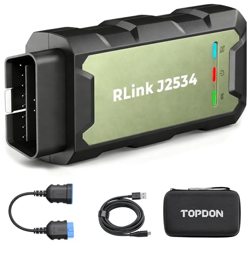
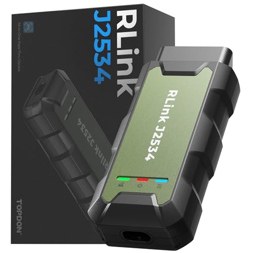
- Advanced VCI Box, Industry-leading J2534 Pass-Thru...
- High-Speed OEM-Level Diagnostics & Programming: Unlock true...
- Coverage for 17 Car Brands & Ultra Reliability: Works...
- User-Friendly RLink Platform & Expert Support: TOPDON’s...
- 6.6 ft USB-C Cable & Portable Storage Case: The RLink J...
Search NHTSA Database for Recalls
Search NHTSA Database for Vehicle Investigations
View Latest Vehicle Investigations
Search NHTSA Database for Vehicle Complaints
View Latest Vehicle Complaints
TSB/Document ID: SD-13-47572A
Replacement Service Bulletin Number:
MFR Communication Date: 2026-01-31
MFR Internal Campaign ID/Software Version:
Communication Type: Service Bulletin/Repair Instructions
NHTSA Components: SERVICE BRAKES
MFR Component System: Trailer
MFR Component Subsystem: ABS
Previous TSB | Next TSB |
Two (2) LAC outputs are available (LAC1 and LAC2) to allow
for independent control of the lift axles.
Traction Help (TH)
The TH function temporarily controls the lift axles of the trailer
such that a higher load is imposed on the drive axles of the
towing vehicle in order to improve traction. The TH function
is only available when configured for automatic LAC.
Maneuvering Help
This function is designed to always reduce the effective
wheelbase of the trailer, regardless of where the lift axles
are located, thereby enabling the trailer to be maneuvered
more easily in confined spaces and reducing the possibility
of tire scrubbing. When Maneuvering Help is configured
and activated, the TABS-6 ADV MC module controls the
appropriate trailer lift axles such that the effective wheelbase
is temporarily reduced. This function is only available up to
a low speed threshold above which the controlled axles will
return to their normal automatic control mode. This function
is only available when configured for automatic LAC.
14
Independent Speed Switch (ISS)
Forcing a lifted axle to lower when the automatic control
dictates that it should be in the lifted position is often a
desirable function and has been integrated in the TABS-6
ADV MC module. LLA is only available when configured for
automatic LAC.
The ISS provides an electrical output signal when a
pre-programmed vehicle speed has been reached. This signal
may be used to fulfill numerous operational requirements
such as locking of the steering axles, rear dump, etc. The
switching “ON” threshold can be set to any speed within the
range 2.5 to 75 mph. The switching “OFF” threshold can
be set to any value within 1.3 mph of the switching “ON”
(minimum hysteresis is 1.3 mph).
Advanced LAC
Advanced LAC is a combined function which offers the
Traction Help (TH) and LLA functions via the same input. The
following logic is implemented (for momentary switch only):
•
TH: the signal is active for less than five (5) seconds
•
LLA: the signal is active for more than five (5) seconds
and less than 10 seconds
•
Normal LAC Mode: the signal is active for more than 10
seconds and will be ignored
Advanced LAC is only available when configured for
automatic LAC.
Lift Axle Status (LAS1 – LAS2)
LAS1 and LAS2 monitor the status of the lift axles to
determine if the axle(s) has been lifted. When enabled for the
Bendix TRSP, the status of the lift axle(s) is used to properly
calculate the trailer weight based on the suspension’s
load input for the optimum TRSP performance. Two (2) lift
axle status inputs are available – LAS1 and LAS2 – each
connected to one (1) or two (2) lift axles.
Tire Inflation System (TIS) Sensing
The TABS-6 ADV MC will monitor the state of the TIS flow
switch and transmit the status upon request through PID-042
of the J1587 protocol. Additionally, it is possible to configure
an ECU controlled lamp to indicate the state of the TIS.
Pad Wear-Sensing
The TABS-6 ADV MC will monitor the state of the pad wear
sensors installed on the air disc brakes. It will activate a
DTC whenever it detects that at least one (1) of the pads
has reached the wear limit.
Speed Pulse
In conventional suspension control systems, the raise/lower
valve is often not reset to the drive position before the vehicle
is moved, and damage can be caused to the suspension
and brakes. To prevent this from happening, the ECU can
be programmed to supply an electrical signal to the raise/
lower valve. When the vehicle exceeds a pre-determined
threshold speed, this signal causes the raise/lower valve
to automatically switch to the drive position. The switching
“ON” threshold can be set to any speed within the range 2.5
to 25 mph, with a signal duration of five (5) to 30 seconds.
The switching “OFF” threshold is pre-set and non-adjustable.
ABS Active
ABS active provides a trailer output signal whenever an ABS
intervention occurs on the trailer. This function is typically
used to provide an ABS active signal to a telematics device.
In addition, with the aid of this function, it is possible to use
the signal to engage a stabilizing function for steering axles.
Roll Stability Program (RSP) Active
RSP active provides a trailer output signal whenever a
Bendix TRSP intervention occurs on the trailer. This function
is typically used to activate a signal to a telematics device
or activate the trailer’s brake lamps via a relay during TRSP.
Steering Axle Lock (SAL)
SAL provides a speed-related output signal that may be
used for connection to a steering axle locking mechanism.
This output signal is a combination of an ISS and ABS
active. While it may be used for the locking of steering axles
via a solenoid valve using an electrical output, it may also
be used for other functions where the operation is to be
speed-controlled.
Voltage Supply
The voltage supply provides power to other systems on the
trailer associated with braking and running gear functions
(brakes, chassis, suspensions, and tires).The power supply
for other functions must use a different power source. The
maximum current available from each configured AUX I/O
output is 1.5 amps.
Tilt Angle
The tilt angle function uses the lateral accelerometer
integrated in the TABS-6 ADV MC module to monitor any
lateral tilting of the trailer during the tipping operation. If
the tilt angle exceeds a programmable threshold, then the
TABS-6 ADV MC module will generate an electrical output
which can be used as a driver warning or tipping intervention.
The warning is only available up to a configurable speed
threshold.
TABS-6 MC LITE does not support tilt angle or lateral
acceleration, but should still follow TABS-6 ADV MC
installation instructions and recommendations.
15
Rear Axle Suspension Dump
21. TROUBLESHOOTING
Some spread-axle trailers are equipped with a rear axle
suspension air bag dump feature to assist with cornering at
low speeds. The TABS-6 ADV MC module may be configured
to use this feature. When this feature is used below a
pre-determined vehicle speed threshold, the ECU will partially
exhaust the rear axle air suspension air bags, and then
re-inflate them when the vehicle speed rises above the predetermined threshold.
Read the entirety of this document before performing any
troubleshooting.
Dome Lamp
Acting as a virtual switch, another device on the CAN
network (e.g. a telematics unit) can request that a dome
lamp, controlled by an auxiliary output on the TABS-6 ADV
MC module, can be turned on.
The dome lamp can be configured to automatically turn off,
regardless of the state of the virtual switch, if the TABS-6
ADV MC module detects that the trailer is moving above a
configured speed. This feature can be turned off by setting
the speed to 0 mph.
NOTE: The dome lamp needs to be hard-wired to an auxiliary
output on the TABS-6 ADV MC module.
Diagnostic information is available using ACom Diagnostic
Software, TRDU, or the TIM.
IMPORTANT
Bendix®-brand Electronic Control Units (ECUs) are
not designed to store data for purposes of accident
reconstruction, and Bendix® ACom® Diagnostic Software
is not intended to retrieve data for purposes of accident
reconstruction. Bendix makes no representations as to
the accuracy of data or video retrieved and interpreted
from ECUs for purposes of accident reconstruction.
Bendix does not offer accident reconstruction services
or interpretation of stored data. Bendix ECUs are not
protected from fire, loss of power, impact damage,
or other conditions that may be sustained in a crash
situation and may cause data to be unavailable or
irretrievable.
Door Status
ACom Diagnostic Software
The TABS-6 ADV MC module monitors the status of the
external door switch connected to one (1) of the auxiliaries
and broadcasts the status of the switch through TI-CAN. It is
also possible to configure the broadcast of the status through
PID 379 of the J1587 protocol on PLC.
ACom Diagnostic Software is a PC-based program that is
designed to meet RP1210 industry standards developed by
the Technology and Maintenance Council (TMC). This software
provides the technician with access to all available system
diagnostic information, including:
•
Electronic Control Unit (ECU) information
•
Diagnostic Trouble Codes (DTCs) and repair information
•
DTC reports
To search DTCs and receive additional troubleshooting
support, refer to B2Bendix.com > Services & Support >
Diagnostic Trouble Code Search.
For additional information on ACom Diagnostic Software and
to purchase the software, refer to B2Bendix.com.
16
Trailer Remote Diagnostic Unit (TRDU) Tool
How the TRDU Tool Operates
The Bendix TRDU tool provides the technician with a visual
indication of ABS component DTC information. The TRDU
tool is specifically designed for use with Trailer ABS systems
and Bendix makes no claims for its operation and/or usability
with other brands of trailer ABS.
When the TRDU tool is plugged into the adapter – and the
adapter/TRDU tool is installed between the trailer connector
and the J560 connector of the towing vehicle that has the
ignition on – all the LEDs will illuminate, and the green LED
will flash four (4) times to indicate communications have
been established.
LED lights
illuminate DTCs
(10 LEDs)
If the ABS ECU has no active DTCs, only the green LED will
remain illuminated.
If the ABS ECU has at least one (1) active DTC, the TRDU tool
displays the first DTC by illuminating the red LEDs, indicating
the malfunctioning ABS component and its location on the
vehicle. See Figure 12.
Figure 10 – TRDU Tool
Features of the Bendix TRDU Tool
The TRDU tool attaches to a 7-pin-to-7-pin adapter (See Figure
11) and then into the J560 connector of the towing vehicle.
The TRDU tool communicates across PLC and allows the
technician to:
•
roubleshoot ABS system component problems using
T
DTC reporting via LEDs.
•
eset DTCs on ABS ECUs by holding a magnet over
R
the reset of the TRDU tool for less than six (6) seconds.
Figure 12 – TRDU Tool Display
NOTE: The TRDU tool does not cover all possible DTCs.
ACom Diagnostic Software should be used as the primary
diagnostic tool.
To the Towing
Vehicle
J560
Connector
LED lights
illuminate DTCs
(10 LEDs)
To the Trailer
Connector
Figure 11 – TRDU Tool and Adapter
Adapter
LED DTCs
VLT ECU SEN MOD1 MOD2 -
Power
ABS Controller
Wheel Speed
Sensor
Modulator 1
Modulator 2
MOD3 LFT RHT ADD ODO -
Example: If the
DTC is "Right
Additional
Sensor", the
TRDU™ tool
will display
one green and
three red LEDs
Modulator 3
Left
Right
Additional
Odometer
LEDs
Green
VLT
Blue
ODO
All others are Red
Figure 13 – DTCs using the TRDU Tool
17
If there are multiple DTCs on the ABS system, the TRDU
tool will display one (1) DTC first, then once that DTC has
been repaired and cleared, the next code will be displayed.
The TRDU tool repeatedly blinks out the mileage stored
once communications have been established. By counting
the sequence of blinks and/or strobes on the blue LED, the
odometer reading is given.
•
VLT (Flashing indicates either an over- or under-voltage
condition)
To pinpoint the root cause and to ensure the system DTC is
properly corrected the first time, additional troubleshooting
may be necessary.
NOTE: When a TRDU tool is connected to a system
with a TABS-6 ADV MC module, and has established
communications, the ECU will use the ABS indicator lamp
to blink codes for all active DTCs.
TRDU Tool Reset Function
The magnetic reset switch is located by the letter "B" in the
Bendix logo on the top of the TRDU tool. When a magnet
(with minimum of 30 gauss) is held over the switch for less
than six (6) seconds, the "clear DTCs" command is sent. [If
a magnet is not available, you may use a spare WSS, since
its internal magnet will be sufficient.]
SERVICING THE TABS‑6 ADV MC MODULE
Special considerations need to be taken to ensure the TABS‑6
ADV MC module has been properly installed on the trailer.
•
Location and orientation of the module
•
Correct plumbing of the module
•
Correct deflection sensor installation (where used)
•
Correct location of the Wheel Speed Sensors (WSS)
•
onfiguration of the ECU for the ABS and the Bendix
C
TRSP system parameters
•
Installation test to verify proper installation of the
ABS/TRSP systems
Incorrect installation of the TABS‑6 ADV MC module
system can result in impaired ABS and TRSP system
functions. It is the responsibility of the end-user to
ensure the TABS‑6 ADV MC module has been installed
correctly and tested as per the Bendix recommended
installation guidelines and system drawings.
Additionally, it is recommended at the end of any inspection
that the technician switches off and restores the power to
the ABS ECU, and then re-checks the ABS indicator lamp
and TRDU tool to see if they indicate any remaining DTCs.
Prior to performing service to the TABS‑6 ADV MC module,
always perform the following steps:
Bendix Trailer Information Module (TIM)
2. I deally, before removing the module, use ACom Diagnostic
Software to save the configuration to the desktop. After
the module has been replaced, the technician can restore
the previous configuration settings.
The Bendix TIM is a display device that combines the
functionality of system diagnostics with the ability to display
and store other trailer-related information of value to an
operator, driver, or workshop. Maximum benefit is obtained
from the TIM functionality when it is mounted on the trailer
so that it is able to record events that occur during driving.
Alternatively, it may also be used as a workshop tool to access
diagnostic information, to check the configuration, or to run
an installation test. In all cases, the TIM is connected to the
J1939 EC5V TI (CAN) connection of the auxiliary connector
which supplies the necessary information.
Figure 14 – Trailer Information Module
18
1. F
ollow all industry safe maintenance practices including
those on page two (2) of this document.
3. Turn the power off.
4. Drain the air pressure from all reservoirs.
5. R
emove as much contamination as possible prior to
disconnecting electrical connections and air hoses.
6. N
ote the TABS‑6 ADV MC module's mounting position
on the vehicle.
Removing the TABS‑6 ADV MC Module
1. O
pen the end covers by sliding the locking tabs to the
left. If the module is to be reinstalled, retain the covers.
2. D
isconnect the 7-pin ECU connector, the 12-pin auxiliary/
diagnostic harness (if present), and the 2-pin WSS
connectors, depending on the configuration, and any
additional harness present on connector 2.3 or 2.4.
3. M
ark for reinstallation and then remove all air hoses
connected to the TABS-6 ADV MC module.
4. R
emove the TABS-6 ADV MC module from the vehicle
by removing the mounting fasteners.
Servicing the Control Port Filter
The TABS-6 ADV MC module has an in-line filter in the
control port (See Figure 2). This filter should be inspected
and cleaned (if any contamination is found), every four (4)
months, 34,000 miles, or 1,200 operating hours. For severe
applications, this inspection interval may be reduced. If the
filter is found to be damaged, install a replacement. The
filter should also be inspected as part of any troubleshooting
where the service brakes are slow to apply and other possible
causes have been ruled out.
Installing the TABS-6 ADV MC Module
All service replacement parts for the TABS‑6 ADV MC
module are configured specifically by part number.
As mentioned in the Servicing the Bendix TABS‑6 ADV
MC Module section, ideally, before removing the module,
use ACom Diagnostic Software to save the configuration
to the desktop. The technician can use ACom diagnostics
to restore the previous configuration settings.
Always verify that the correct service replacement ECU is
being installed for the original TABS‑6 ADV MC module.
To verify proper installation, perform the installation
test using the ACom Diagnostic Software or use the
Bendix TIM.
NOTE: Inspect all components, including the replacement
of the TABS‑6 ADV MC module, for any external damage,
such as cracked valve ports, electronic housings, etc. Any
components found to be damaged should not be installed
on the vehicle and must be replaced.
1. T
he TABS‑6 ADV MC module should be installed with
the following considerations (See Figures 15 through 18):
•
ith the exhaust port facing downward and
W
unobstructed with significant free space below
(>1 in.).
•
ithin ± 100 in. (2.5 m) of the center of the axle(s) for
W
properly balanced brake applications.
•
ithin ± 2 in. (5.1 cm) from the center line of the
W
trailer (default).
NOTE: a left/right offset greater than ± 2 in. (5.1 cm)
may have been programmed in the ECU and can be
verified using the ACom Diagnostic Software.
•
he yaw angle should be ± 10° as measured from the
T
center line of the trailer.
•
he pitch angle should be ± 10° as measured from a
T
flat horizontal plane.
•
he roll angle should be within ± 5° as measured from
T
a flat horizontal plane.
5°
5°
Vertical Orientation
(Roll Angle)
Must be within Five (5)
Degrees of Vertical
Figure 15 – Installation on the Trailer (Vertical)
If replacement hardware is needed, use Class-8 steel
M10 x 1.5 lock nuts and washers for frame-mounting.
Inspect the location selected for installation and clean
as necessary.
19
10°
10°
Longitudinal Orientation
(Pitch Angle)
Must be within TEN (10)

- CEL Doctor: The ANCEL AD310 is one of the best-selling OBD II scanners on the market and is recommended by Scotty Kilmer, a YouTuber and auto mechanic. It can easily determine the cause of the check engine light coming on. After repairing the vehicle's problems, it can quickly read and clear diagnostic trouble codes of emission system, read live data & hard memory data, view freeze frame, I/M monitor readiness and collect vehicle information.
- Sturdy and Compact: Equipped with a 2.5 foot cable made of very thick, flexible insulation. It is important to have a sturdy scanner as it can easily fall to the ground when working in a car. The AD310 OBD2 scanner is a well-constructed mechanic tool with a sleek design. It weighs 12 ounces and measures 8.9 x 6.9 x 1.4 inches. Thanks to its compact design and light weight, transporting the device is not a problem. The buttons are clearly labelled and the screen is large and displays results clearly.
- Accurate Fast and Easy to Use: The AD310 scanner can help you or your mechanic understand if your car is in good condition, provides exceptionally accurate and fast results, reads and clears engine trouble emission codes in seconds after you fixed the problem. This device will let you know immediately and fix the problem right away without any car knowledge. No need for batteries or a charger, get power directly from the OBDII Data Link Connector in your vehicle.
- OBDII Protocols and Car Compatibility: Many cheap scan tools do not really support all OBD2 protocols. AD310 scanner as it can support all OBDII protocols such as KWP2000, J1850 VPW, ISO9141, J1850 PWM and CAN. This device also has extensive vehicle compatibility with 1996 US-based, 2000 EU-based and Asian cars, light trucks, SUVs, as well as newer OBD2 and CAN vehicles both domestic and foreign. Pls confirm with our customer service whether it is compatible with your vehicle before purchasing.
- Home Necessity and Worthy to Own: This is an excellent code reader to travel or home with as it weighs less and it is compact in design. You can easily slide it in your backpack as you head to the garage, or put it on the dashboard, this will be a great fit for you. The AD310 is not only portable, but also accurate and fast in performance. Moreover, it covers various car brands and is suitable for people who just need a code reader to check their car.

- Multi-Functions - Practical Multi-Functions OBD2 code reader features built-in OBD2 DTC lookup library, which help you to determine the cause of the engine light, read code, erase code, view freeze frame, I/M ready, vehicle information, data flow, real-time curve, get vehicle speed information, calculate load value, engine coolant temperature, get engine speed.
- Wide Capability - Supports 9 protocols compatible with most 1996 US-Based, 2000 EU-Based and Asian cars, and newer OBD II & CAN domestic or import vehicles. Supports 6 languages - English,German, Dutch, Spanish, French, Italian.
- 2.8" LCD Display - Designed with a clear display 2.8" Large LCD screen - white backlight and contrast adjustment. No need any battery or charger, OBD reader gets the power directly from your vehicle through the OBDII Data Link Connector.
- Compact Design - Car diagnostic scanner is equipped with a 2.5 feet long cable and made of a very thick flexible insulator.There are 6 buttons on OBD2 Scanner:scroll up/down,enter/exit and buttons that quick query VIN vehicle number& the DTC fault code.
- ABS / Airbag codes NOT Supported - It is able to read and clear check engine information which is part of OBDII system, but it cannot work with non-OBDII systems, including ABS / Airbag / Oil Service Light, etc.

- 【Your Personal CEL Doctor – Read & Clear Engine Codes】The NT301 OBD2 scanner lets you read diagnostic trouble codes (DTCs), check em-issions readiness, turn off your Check Engine Light (CEL) or MIL, reset monitors, and view live data streams. It retrieves your vehicle's VIN instantly. Like all standard OBD2 scanners, it clears codes only after repairs are completed—if the issue persists, the code will return. Designed for DIYers who want to understand what’s really going on under the hood.
- 【Easy Code Reading – Just Plug & Play】Simply plug into the OBD2 port, turn the ignition to “ON” (engine off), and select the correct menu: Select OBDII-> Wait for seconds-> Select Read codes. For accurate results, ensure your vehicle is compatible and the OBD2 port is free from damage or wiring issues. No batteries needed— powered directly by your car.
- 【Live Data Graphing & Accuracy for Most OBD2 Vehicles】View and log live sensor data in graph form—monitor oxygen sensors, fuel trims, coolant temp, RPM, and more. Spot trends and suspicious values in real time. Compatible with most 1996+ gasoline cars, light trucks, and SUVs sold in the U.S., as well as many 2000+ European and Asian models. Also works on 12V diesel vehicles equipped with OBD2.
- 【S-mog Check Helper – Know Your Readiness Status at a Glance】With dedicated I/M readiness hotkeys and a simple Red-Yellow-Green LED indicator, you’ll instantly know if your vehicle is ready for em-issions testing. Built-in speaker provides audio feedback. No guesswork—just confidence before you head to the test center.
- 【A Must-Have Tool for Every Home Mechanic】Compact, rugged, and ready to use right out of the box. The 2.8” color screen is easy to read, even in daylight. No charging or setup required—just plug into the 16-pin DLC and start diagnosing. Recommended by professional mechanics on YouTube and trusted by DIYers worldwide.
Last update on 2026-03-25 / Affiliate links / Images from Amazon Product Advertising API
This product presentation was made with AAWP plugin.